4-65a SE Amp: Building process (Part 2)

Further progress today: more cabling done for the SSHV2 boards and A2 current raw supplies for the 46 driver gyrators….


4-65a SE Amp: 46 filament supply tested

20130506-131030.jpg

Finished the second channel and tested the filament supply. The filament array which is formed by two paralleled pairs of 20W 10Ω wirewound resistors gets hot as expected. The array temperature is about 110-126°C at an ambient temperature of 24°C. The anode of the 46 gets to 49°C after 20 min of use and the heatsink stays at 42°C whereas the regulator TO-220 transistors are about 45°C. There is about  30W dissipated on each array. Yes I know, a lot of power but the filament bias is hard to beat in terms of sound in my view.

4-65a SE Amp building process

Some drilling and mounting work done this morning on the 4-65a SE amp breadboard:

During the afternoon, I managed to wire a filament supply for one channel 46 driver. Tested and working ok, now can move to the next one:

4-65a SE Amplifier: testing filament regulators

The Rod Coleman Filament Regulators were already tested in the New Year. It seems a long time indeed. Here is a selection of pictures after fitting the regulators in their heat-sinks and doing a final test before assembly:

4P1L pentode driver (continued)

4P1L Pentode Driver v01After the initial tests done with the 4P1L in pentode mode and filament bias, I thought a bit about how this driver could be implemented in practice. I may try this configuration in my 4-65a SE amp, but am not urged by this at all.

The screen supply is formed by a gas valve (SG3S) which provides a very stable reference when feed by a CCS. In this case the cascoded pair M3 and M4 will provide in conjunction with R4 and U2 a very low noise screen current to U1.  R9 has to be adjusted on test to set a current of about 15mA on the CCS. The 4P1L will draw 1.8mA at 81V as screen current, so R4 may also need adjustment to set the right operating point.

The driver should provide about a gain of 150. Driving easily a transmiting vale (or why not a 300B 🙂 ) in class A2 with this configuration. My tests showed a maximum THD of about 0.27% at 200Vpp.

Gain could be reduced if needed by tweaking the RL. And if stacked supplies are not used, then a single +400V supply could be used with additional dissipation across the reference currents (M1 and M3/M4).

Keep thinking…


46 DHT driver final tests

20130105-125459.jpg

Having built the 4P1L filament bias driver stage in a breadboard, I now have the sufficient voltage swing to drive the 46 to maximum sweep. In my 4-65a SE amp, a maximum of 200Vpp is required to drive the amp into class A2.

The following tests conditions were used:

  • 4P1L first stage:
    • DN2540 gyrator in mu follower output
    • 220nF/450V Capacitor coupled into 46 driver
    • Filament bias: 15 ohms, Vgk=-10V
    • Vsupply=355V and Va0=210V
    • Output set to about 30-32Vpp to drive 46 at 200Vpp
  • 46 driver stage:
    • IXYS 01N100 gyrator in mu follower output
    • Load impedance is 100K (Pete Millett’s interface)
    • Filament bias: 10 ohm / 100W Vgk=-17V
    • Vsupply=355V and Va0=204-208V
    • Output set to 200Vpp

I tested 28 valves. Just a few of my lot are NOS. The average THD was about 0.4-0.5% but a good selection of 8 valves (mainly Sylvania NOS) provided a consistent 0.18% THD:

4P1L into 46 driver test2Happy now with the initial tests and selection of 46 pairs for the amplifier, I can now continue with the build…

4-65a SE Amp: refining the 46 driver


I did some tests today and looked at minimising distortion of this 46 driver in filament bias and found that Va=230V (instead of 184V) to provide best performance:20130101-134450.jpgFilament bias resistor array is now laid out horizontally to improve the dissipation of heat.

Here is the performance (0.05% at 17Vrms) at maximum drive input from my audio test set:

46 Driver Test2 17Vrms


4-65a SE Amp: testing the 46 driver

46 driver breadboarded. The mu-follower gyrator, the filament bias resistor array and the nice teflon UX5 socket from Jakeband. The filament bias resistor array is formed by 4 10Ω 20W dale wirewound resistors. These get very hot so probably need to think an alternative layout or further resistors in parallel:20121231-191140.jpgThe performance is very good. I just picked up a random 46 from my stock and biased it at 204V (which is the operating point in my design) achieving less than 0.05% at 10Vrms. Need to re-run this test to see how will perform at 70Vrms:46 Driver Test1 10Vrms

20121231-191152.jpg

20121231-191204.jpg

Using my spice model created from a good 46 valve, THD should be around 0.15% at 200Vpp with a 100K load and performance is great to loads down to 100 ohms. Clearly the load in A2 will change from high impedance to some kΩ so this driver should maintain outstanding linearity all the way through:
46 driver THD

4-65a SE Amp: 46 Driver Gyrator

 A day of PCB etching

20121230-194358.jpg
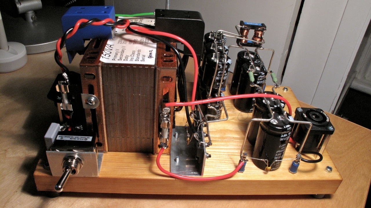
After a lot of work today in designing many PCBs, I finally got a pair of mu-follower MOSFET gyrators for the 46 driver stage.  The driver has to provide very low impedance to operate the 4-65a output valve in class A2. The gyrator in mu-follower configuration will enable the right bias point as the amplifier is DC coupled as well as maximum signal (and current in A2) with minimum distortion.

Many don’t like sand at all in their amplifiers. I have a lot of experience with gyrators and CCS loads in pre-amps and drivers as well. I have to say that with MOSFETs gyrators the sound is really nice. For an A2 driver, not many options are available and the gyrator is a great choice for this job.

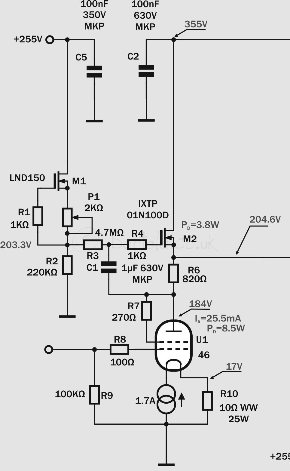
I built two PCBs (one per channel) and the circuit is the classic depletion-mode MOSFET gyrator based on the high-voltage IXTP01N100D. I guess that a DN2540 should work as well here but I’ve been saving the IXYS for this occasion. The reference voltage for the anode bias point is provided by the CCS formed by M1 (LND150) which provides a higher impedance in AC improving the frequency response of the gyrator.

4-64-65a driverThe 46 is operating in triode-mode and filament bias with a Rod Coleman filament regulator. R6 is approximately 1/gm and output voltage is set by P1 to achieve the 4-65a bias point as the amplifier has stacked power supplies given coupling is DC, so no capacitors in the path to the grid.

Next: some tests on these gyrators and the filament boards…


4-65a SE Amp: 46 Driver Raw Supply

One more filament raw supply completed today: the 46 driver in filament bias. This driver stage requires 26V @ 1.7A due to the filament bias requirements. Yes, nearly 45W in the filament but will provide a fantastic driver stage with the 46 triode-strapped and filament bias to avoid any nasty capacitor in the signal path.

The power supply design is very simple and follows Rod Coleman’s recommendations for the DHT filament regulators. One drawback in this version, compared to the output stage raw supply, is that this will be pure capacitor filtering with no help of a choke to reduce the input current pulses.

4-65a 46 driver filament raw


The split-bobbin 150VA transformer provides sufficient current for the capacitor input filtering stage. The DSB10I45 (Schottky 45V/10A) bridge is also mounted on a “L” shape aluminium piece.IMG_3591

The capacitor arrays are soldered to a thick bare wire which provides structure and simplifies connections between components: IMG_3592

I was initially concerned that without shielding the high-current pulses may introduce some noise in the output as F2 fuse is mounted on the transformer frame so the wire is routed back and forward to that point. Reality is that the hum level is very low. I measured 16.4mV peak-to-peak at full load.