
It’s been a while indeed. Mostly busy with my day job and family. However, spare time is dedicated to synthesisers – I’m designing and building modules for Eurorack – and playing and listening to music.
I’ve been asked about the GU-50 triode curves. I have misplaced them, however I have something even better to share which is the accurate model created for this great valve.

Here are the pentode curves at different screen voltages with the matching model:


Here are the models for you to use:
***************************************************
.SUBCKT GU50-pentode-300V 1 2 3 4 ; A G2 G1 C;
*      Extract V3.000
* Model created:  4-Jun-2016
* Version 2
*
* Curve tracing and model by Ale Moglia (valves@bartola.co.uk)
* (c) 2016 Bartola Valves
* www.bartola.co.uk/valves
*
* Derk Model
*
X1 1 2 3 4 BTetrodeD  MU=  6.26 EX=1.296 kG1= 380.1 KP=  22.3 kVB =  437.3 kG2=92411.5
+Sc=.81E+01 ap=  .100 w=     0. nu=   .00 lam=    39.4
+ Ookg1mOokG2=.262E-02 Aokg1=.99E-06 alkg1palskg2=.262E-02 be=  .080 als=173.46 RGI=2000
+ CCG1=13.0P  CCG2 = 0.0p CPG1 = 0.0p  CG1G2 = 0.1p CCP=10.0P  ;
.ENDS

****************************************************
.SUBCKT BTetrodeD 1 2 3 4; A G2 G1 C
*
* NOTE: LOG(x) is base e LOG or natural logarithm.
* For some Spice versions, e.g. MicroCap, this has to be changed to LN(x).
*
RE1  7 0  1MEG    ; DUMMY SO NODE 7 HAS 2 CONNECTIONS
E1 7 0 VALUE=
+{V(2,4)/KP*LOG(1+EXP(KP*(1/MU+V(3,4)/SQRT(KVB+V(2,4)*V(2,4)))))}
E2   8 0 VALUE = {Ookg1mOokG2 + Aokg1*V(1,4) - alkg1palskg2/(1 + be*V(1,4))}
E3   9 0 VALUE = {Sc/kG2*V(1,4)*(1+tanh(-ap*(V(1,4)-V(2,4)/lam+w+nu*V(3,4))))}
G1   1 4 VALUE = {0.5*(PWR(V(7),EX)+PWRS(V(7),EX))*(V(8)-V(9))}
G2   2 4 VALUE = {0.5*(PWR(V(7),EX)+PWRS(V(7),EX))/KG2 * (1+ als/(1+be*V(1,4)))}
RCP  1 4  1G      ; FOR CONVERGENCE	A  - C
C1   3 4  {CCG1}   ; CATHODE-GRID 1	C  - G1
C4   2 4  {CCG2}   ; CATHODE-GRID 2	C  - G2
C5   2 3  {CG1G2}   ; GRID 1 -GRID 2	G1  - G2
C2   1 3  {CPG1}  ; GRID 1-PLATE	G1 - A
C3   1 4  {CCP}   ; CATHODE-PLATE	A  - C
R1   3 5  {RGI}   ; FOR GRID CURRENT	G1 - 5
D3   5 4  DX      ; FOR GRID CURRENT	5  - C
.MODEL DX D(IS=1N RS=1 CJO=10PF TT=1N)
.ENDS BTetrodeD
And here is the triode model:
****************************************************
.SUBCKT GU50-triode 1 2 3; A G C;
*      Extract V3.000
* Model created:  4-Jun-2016
*
*
* Curve tracing and model by Ale Moglia (valves@bartola.co.uk)
* (c) 2016 Bartola Valves
* www.bartola.co.uk/valves
*
X1 1 2 3 TriodeK MU=  6.18 EX=1.380 KG1= 448.2 KP=  22.3 KVB=  700. RGI=2000
+ CCG=0.0P  CGP=0.0P CCP=0.0P  ;
.ENDS

****************************************************
.SUBCKT TriodeK 1 2 3; A G C
*
* NOTE: LOG(x) is base e LOG or natural logarithm.
* For some Spice versions, e.g. MicroCap, this has to be changed to LN(x).
*
E1 7 0 VALUE=
+{V(1,3)/KP*LOG(1+EXP(KP*(1/MU+V(2,3)/SQRT(KVB+V(1,3)*V(1,3)))))}
RE1 7 0 1G
G1 1 3 VALUE={0.5*(PWR(V(7),EX)+PWRS(V(7),EX))/KG1}
RCP 1 3 1G    ; TO AVOID FLOATING NODES IN MU-FOLLOWER
C1 2 3 {CCG}  ; CATHODE-GRID
C2 2 1 {CGP}  ; GRID-PLATE
C3 1 3 {CCP}  ; CATHODE-PLATE
D3 5 3 DX     ; FOR GRID CURRENT
R1 2 5 {RGI}  ; FOR GRID CURRENT
.MODEL DX D(IS=1N RS=1 CJO=10PF TT=1N)
.ENDS TriodeK
You can download the files from here:
Awesome. Lots of upgradeable China amps using those.
You should check out the EL 802. Peter millet included it in his small signal pentode test via the PL802 which is the 16v heater version . EL802 is 6.3V
http://www.pmillett.com/pentodes.htm
Hi Ale – can you post the triode curves please? I guess you can run them from your code?
Hi Andy,
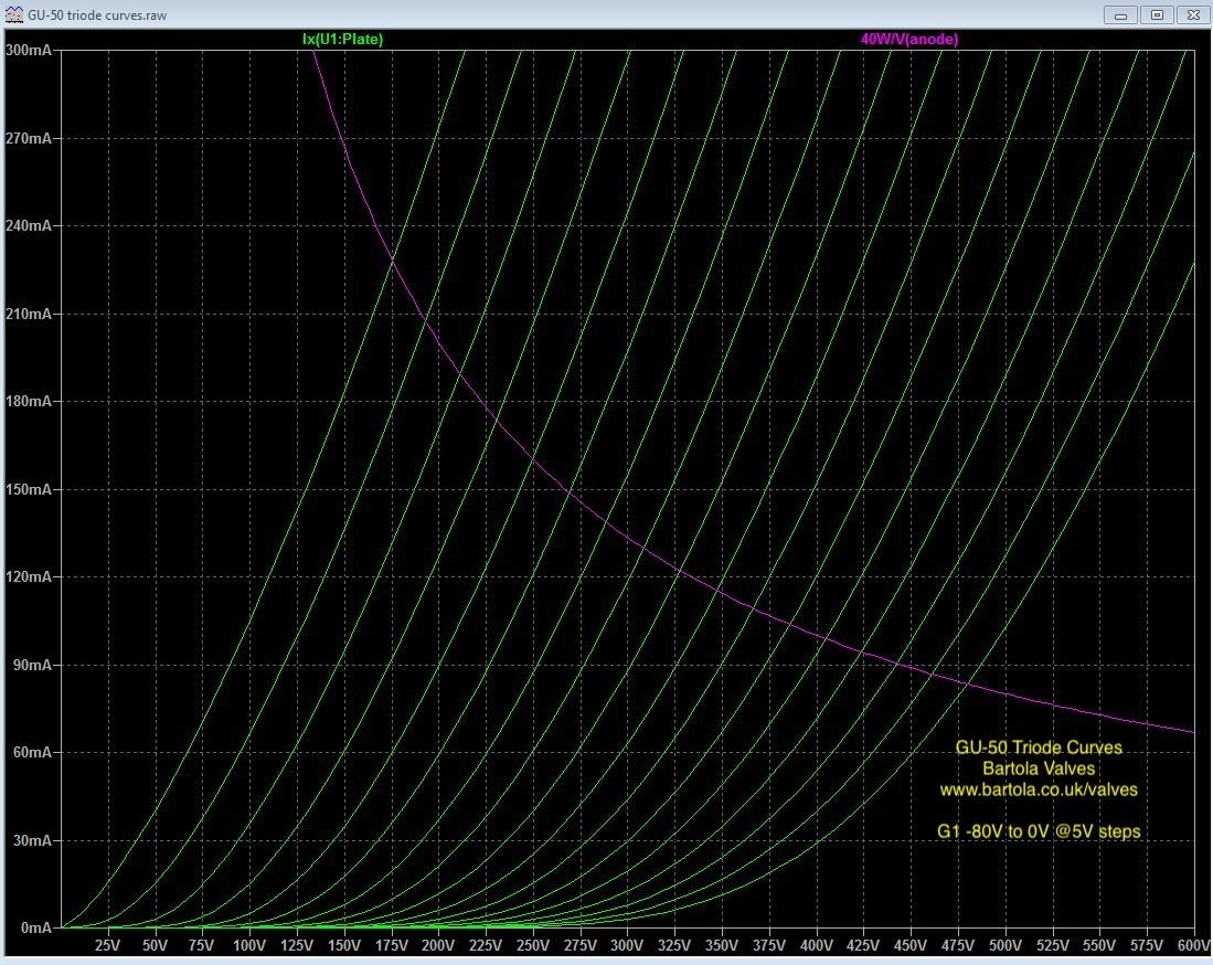
Apologies for late reply. Busy with work. Here are the curves generated from the model. Grid steps are 5V, from -80V to 0V. hope this helps!