
I upgraded the DHT filament regulators to version 4. Rod has released a new kit which introduces temperature compensation for high current filaments. This is a key feature in my 4-65a design and I shall explain why:
Tag: 4-65a SE
4-65a SE Amp: output valve
One of the output 4-65a was actually a military JAN-8165. Wanted to test a pair of them but in the rush of building the amp I ended up with a mixed of the two. Not an orthodox approach buy who cares! After playing the amp extensively for a couple of weeks I noticed that this valve droped anode current after 1hour or more of playing. Anode current could go down by 10-15mA. Perhaps it has to do with the pin oxidation, but I also suspected on the filament regulator due to the heavy current required on this. The regulator heatsink gets really hot as you can imagine so I was already blaming on the regulator FET before I even suspected on this output valve.


A simple test was to replace this valve by a new NOS 4-65a. I did that and surprised to find that the filament regulator wasn’t to blame. The 4-65a SE filament stayed rock solid at 100mA after 1h30m of fantastic music. Yes, the bass of this SE is unique. It exceeded everything I previously listened to. Is the 46 driver in filament bias? Not sure yet, but hey ho. What an amp!
Adjusting the shunt regulator
One of the problems I found when using the 4-65a SE amp was that my version of the Salas SSHV2 drifted significantly with temperature. This was due to the 01N100D characteristics (see extract from datasheet below). We can see that @ -1.5V VGS the temperature dependency is as much as 50mA/100°C. With the smaller heatsink I had before and the significant voltage drop given raw supply voltage levels this caused a problem:

I then reduced the input raw voltage level to 300V to ease the power dissipation across this FET. This was not sufficient so I proceeded to look at various things on the regulator as described below:
Change log
- Replaced M1 for DN2540. The DN2540 has a better temperature response. The voltage levels now allowed me safely use the DN2540 and no need for a 01N100D.
- Added bigger heatsinks for M1 and M3. Even 2.5W across M1 would need a bigger heatsink if we are looking to run the CCS as high as 90mA.
- Removed TP resistor to allow higher CCS current
- Set CCS current to 85mA
- Load will be now 30mA per channel (30mA each 46 driver valve)
- Set output votage to 270V


All tested well in the workbench. I used an external CCS set at 60mA and the output voltage stabilisation was rock solid at 270V. Temperature of the heat-sink was around 40-45°C after 30min of continuous use.
Back in the 4-65a SE Amp, the raw supply level at full load was 297V. The regulator played nicelly at 270V and the CCS current drifted only 5mA from 90mA down to 85mA after 2 hours of continuous play. The temperature of the CCS increased only to 47°C whereas the shunt FET got up to 54°C given the continuous 7W dissipated on it. I may try to reduce the CCS current a tad to ease here.

Played the amp for about 2 hours and slowly started to appreciate more and more the sweet sound of this beast. Bass has increased significantly in my systems and previously haven’t been able to extract the deep bass out of the SE amp through my Fostex FE167E full range drivers.
I’m really going to enjoy this amp for a while until I start looking at changes. Oh yes, many come to mind, but easy for now. Other projects are awaiting for a long time so far.
Ale
4-65a SE Amp: testing it finally!
The much-awaited moment finally arrived. After yesterday’s driver tests, I did a lot of work this morning to assemble cables and test the output stage. What I clearly know now is that I won’t be needing any heating this winter! What on earth was on my mind when I decided to build this amp? God only knows…
Here are some pictures of the first tests in the workshop and then when I hooked it up to my system downstairs in the sitting room:

26 preamp and 4-65a SE Amp just before testing

Burning in the 4-65a!

Setting output bias

Measuring output
I did a quick measurement of the output THD without burning in the 4-65a or the amp. The operating point is not optimised but clearly shows a nice picture. First of all, the amp is absolutely quiet. The Rod Coleman regulators plus the extensive filtering on all supplies (LCLC and CLCLC) make this the quietest amp I’ve ever made! The distortion is higher than predicted. With the valves at 100mA/540V and with a non-inductive resistor load of 10Ω, the THD is about 2.7% for nearly 6W of pure class A power. Only 4% of the harmonic content is H3 and with a nice H2 component. The footprint of an SE amp is clearly on this amp.

Hooked it downstairs and after a lot of wiring I finally got to play some good records on this amp. I used my 26 DHT preamp. First record to be played was “a love supreme” (John Coltrane). Here are my impressions so far:
- I’m surprised with the bass. It is powerful and not something I was used to in a single ended amp
- Definitely needs some burn-in time. The amp improved after 1 hour of use
- It’s loud! You can get 10W easily in class A2. Very loud for my room!
- The tone is warm and very sweet. you get the sound of the DHT clearly
- Dynamics are its forte. This amp responds very well to them
Some more pictures:

4-65a Amp finished

Cherry red anode!

First time up

A power supply madness!

Input transformers and 46 drivers
Now is time for proper listening after so much work. A real accomplishment and I’m feeling very proud. The amp fits within my cabinet so wife is happy 🙂
4-65a SE Amp: first driver test
 After completing the last power supply, I finally did some real tests on the 4-65A SE amplifier. Given the DC coupled design it is a bit tricky to do the initial calibration. I had to set the operating point of both 46 DHTs by adjusting the anode voltage through the individual gyrator load presets. Also had to balance at the same time the Salas Shunt current and output voltage to the desired levels. After playing a while with it I managed to stabilise the Salas shunt regulator.
Set the 46 to drive the output stage to 200Vpp with a 3.7Vpp (1.33Vrms) input. That is a gain of approximately 54. Here is the distortion profile:
 Breadboard is really quiet with the 50 and 100Hz noise below -95dB. It’s great to see the nice 46 Super Silvertone performing only 0.09% at 200V peak to peak!
Results are promising, just need final tweaks to 600V supply and then hook the 4-65a!
Ale
4-65A SE Amp: A2 grid current supply
Finished today the penultimate power supply of the 4-65a SE amplifier. This one is the A2 grid current one and doesn’t need a lot of filtering as the 46 driver gyrator will do most of that job. The DC stacked design of this amplifier will allow an independent loop of the A2 current between this supply and 4-65a grid-cathode.
Just only one more supply to go and I’m done!!!

40uF and 8uF oil caps

Mains transformer and bridge recitfier

Main switch and bridge rectifier

Choke and output connector
4-65a SE Amp building process
Some drilling and mounting work done this morning on the 4-65a SE amp breadboard:

Filament bias resistor array

Closer view of the filament bias resistor array

Mounting pilars for the SSHV2 regulators

46 valve sockets

Closer view of the 46 valve sockets

46 sockets, filament bias array and filament and HV supply connectors
During the afternoon, I managed to wire a filament supply for one channel 46 driver. Tested and working ok, now can move to the next one:

Filament regulator with its heat-sink at the back, anode loads and the 46 DHT drivers at the centre.

46 DHT driver under test. Gyrator anode load can be seen at the front

46 DHT driver
4-65a SE Amp: HV3 supply
 Building the HV3 (+330V Supply)

I could easily say that by now I’m tired of building power supplies. Yes, I’m and fundamentally can’t see the day when I get to fire up this amplifier.
Filament supplies and three stacked power supplies is the price I’m paying to get a completely cap-less and DC coupled A2 amplifier. I guess that my analysis once completed will be made with full perspective of every single implication of this amp: iron, heat and weight. Yes sir, this is a heavy-weight challenger.
 I guess that this specific HT power supply design is quite flexible as could be easily reused in many of the projects I have in mind, which unfortunately keep growing.
Good thing is though, I can make these supplies pretty quickly, but don’t do this at home ok? There is serious HT involved. I don’t have pets or kids (but do have a wife) and these supplies should be hidden and away from any poking curious finger.
The final design is similar as the one used before. Could be adapted to choke input, but with the components I had at hand, this supply is very well filtered. It provides only 15mV ripple noise which at 330V is a lovely noise floor around -87dB:
 The mains transformers are Weiss (excellent quality) which has screened windings. Instead of having a full Graetz valve rectifier and waste more heat (and use more damper valves), the rectifier is hybrid using a pair of UF4007. Capacitors are oil and polyester ones for the output HF decoupling on each rail. Each channel will feed a Salas SSHV2 shunt regulator which will provide the stable DC reference for the 46 driver stage and bias point for the output 4-65a stage.
Bad news is that, there is one supply left to be built before I can test at least one channel!
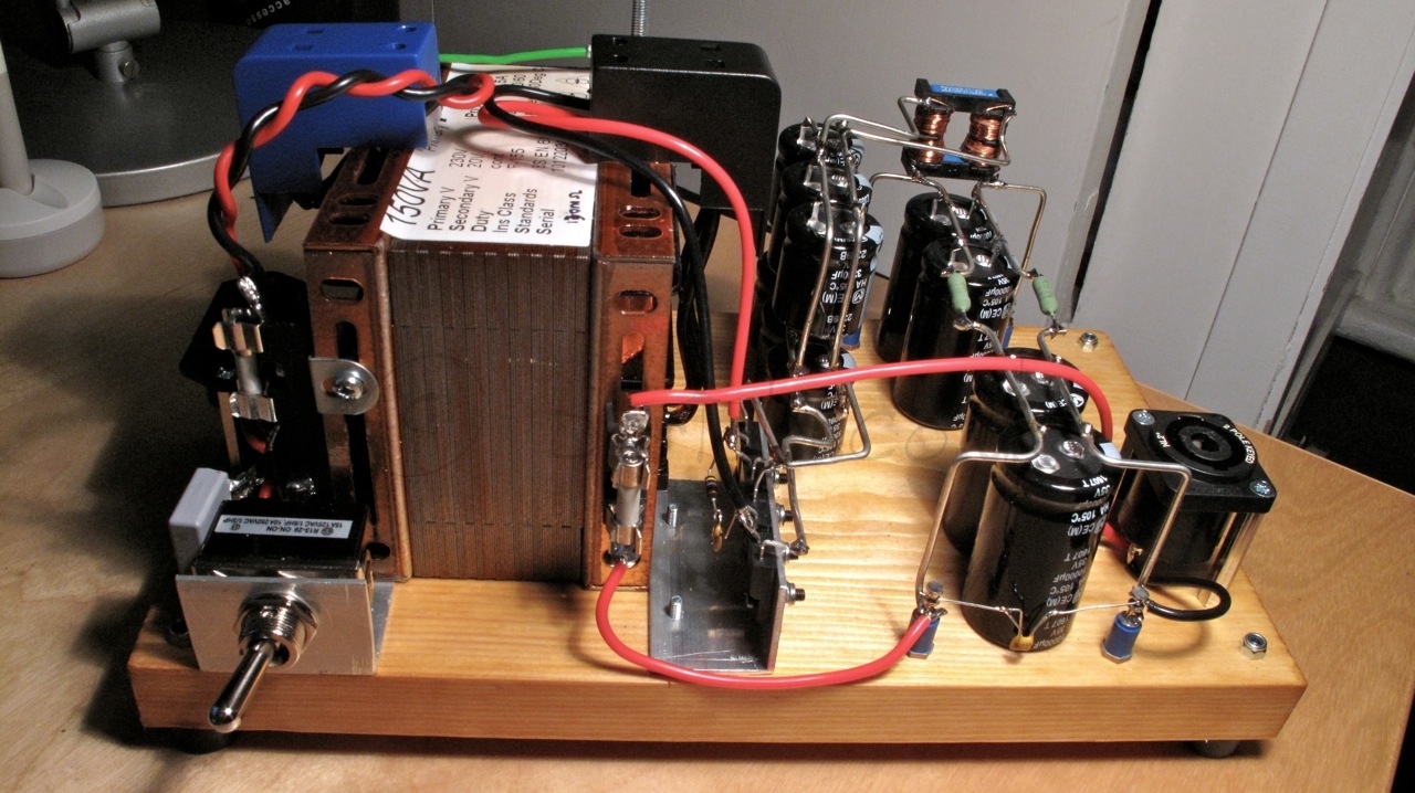
4-65a SE Amp: 46 Driver Raw Supply
One more filament raw supply completed today: the 46 driver in filament bias. This driver stage requires 26V @ 1.7A due to the filament bias requirements. Yes, nearly 45W in the filament but will provide a fantastic driver stage with the 46 triode-strapped and filament bias to avoid any nasty capacitor in the signal path.
The power supply design is very simple and follows Rod Coleman’s recommendations for the DHT filament regulators. One drawback in this version, compared to the output stage raw supply, is that this will be pure capacitor filtering with no help of a choke to reduce the input current pulses.

The split-bobbin 150VA transformer provides sufficient current for the capacitor input filtering stage. The DSB10I45 (Schottky 45V/10A) bridge is also mounted on a “L” shape aluminium piece.
The capacitor arrays are soldered to a thick bare wire which provides structure and simplifies connections between components: 
I was initially concerned that without shielding the high-current pulses may introduce some noise in the output as F2 fuse is mounted on the transformer frame so the wire is routed back and forward to that point. Reality is that the hum level is very low. I measured 16.4mV peak-to-peak at full load.