3A5 DHT (Continued)

Lars requested the paralleled triode curves. Here they are:

3A5 RCA 2 triodes SMALL And the SPICE model which is more accurate than my previous version:3A5 2 triodes spice model


* Created on Sat Jan 19 15:50:19 GMT 2013 using tube.model.finder.PaintKIT
* model URL: http://www.bartola.co.uk/valves/
* Created by Ale Moglia 2013 valves@bartola.co.uk
*————————————————–
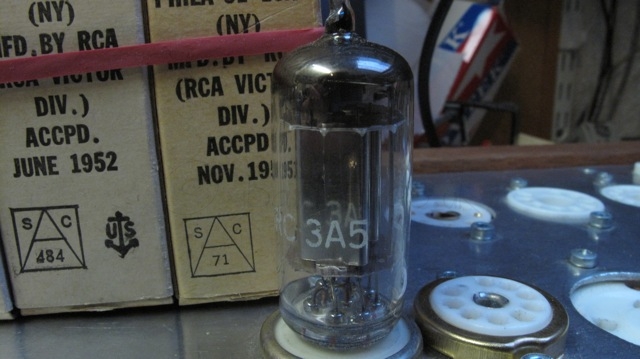
.SUBCKT TRIODE_3A5-2 SMALL 1 2 3 ; P G K ;
+ PARAMS: CCG=.9P CGP=3.2P CCP=1.0P RGI=2000
+ MU=12.46 EX=1.3857 KG1=1965.0 KP=132.0 KVB=1.875 VCT=-1.6 ; Vp_MAX=200.0 Ip_MAX=0.032 Vg_step=2.0
*————————————————–
E1 7 0 VALUE={V(1,3)/KP*LOG(1+EXP(KP*(1/MU+(VCT+V(2,3))/SQRT(KVB+V(1,3)*V(1,3)))))}
RE1 7 0 1G
G1 1 3 VALUE={(PWR(V(7),EX)+PWRS(V(7),EX))/KG1}
RCP 1 3 1G ; TO AVOID FLOATING NODES
C1 2 3 {CCG} ; CATHODE-GRID
C2 2 1 {CGP} ; GRID=PLATE
C3 1 3 {CCP} ; CATHODE-PLATE
D3 5 3 DX ; FOR GRID CURRENT
R1 2 5 {RGI} ; FOR GRID CURRENT
.MODEL DX D(IS=1N RS=1 CJO=10PF TT=1N)
.ENDS
*$

Looking at distortion, as expected the pair of paralleled triodes performs better than a single triode:

3A5 paralleled THD Vo=10Vrms

3A5 DHT

IMG_3621
The 3A5 DHT is another interesting valve to bear in mind.  Many have used them successfully even in a phono stage. Great examples are Dmitry Nizh’s DHT phono stage and Sheldon’s. I will probably use them as well at some point.

Can you hear the microphonics SMALLWell, many DHT have been dismissed over the years due to their microphonic sensitivity. True, they are more microphonic, but this is manageable. Look at the 4P1L for example. I built a great preamp a couple of years ago and played around with the mechanics of the preamp to quiet it down. And I managed to, succesfully (as many have as well). The 4P1L sounds fantastic, despite so many turning it down because of its natural singing skills 🙂 Now, 4P1L is looked after, many are building DHT preamps and even full DHT amplifiers.

Looking at the specifications of the 3A5, we can see that the heater is attractive to be used with rechargeable batteries. Well, at least 220mA @ 1.4V is manageable. Key specs are:

  • Mu of 15
  • Anode resistance (ra) is 8,300Ω.
  • Anode dissipation (Pa) is 500mW per valve.
  • Vf=1.4V / If =220mA (paralleled filaments)
  • Transconductance (gm):  1.8mA/V
  • Maximum anode voltage: 135V

How linear is this DHT? Let’s look at the curves first:

Continue reading “3A5 DHT”

4P1L pentode driver (continued)

4P1L Pentode Driver v01After the initial tests done with the 4P1L in pentode mode and filament bias, I thought a bit about how this driver could be implemented in practice. I may try this configuration in my 4-65a SE amp, but am not urged by this at all.

The screen supply is formed by a gas valve (SG3S) which provides a very stable reference when feed by a CCS. In this case the cascoded pair M3 and M4 will provide in conjunction with R4 and U2 a very low noise screen current to U1.  R9 has to be adjusted on test to set a current of about 15mA on the CCS. The 4P1L will draw 1.8mA at 81V as screen current, so R4 may also need adjustment to set the right operating point.

The driver should provide about a gain of 150. Driving easily a transmiting vale (or why not a 300B 🙂 ) in class A2 with this configuration. My tests showed a maximum THD of about 0.27% at 200Vpp.

Gain could be reduced if needed by tweaking the RL. And if stacked supplies are not used, then a single +400V supply could be used with additional dissipation across the reference currents (M1 and M3/M4).

Keep thinking…


a C3g driver…

Sunday morning and my brain already started with a lot of activity early today. Should be the other way round. I spent all week working and weekends should be about relaxation, but can’t help it 🙂 Before going up to the workshop and continue with the 4-65a SE amplifier build, I put into work some of these ideas that are flying around.

The 46 filament bias driver with its hefty supply will be “the driver” for the 4-65a, yes, no doubt. I may want to try some other combinations such as 4P1L pentode in filament bias, or why not some other drivers as 6e5p, C3g and D3a. All these are brilliant candidates. But final judge should be my ears. We all know that what looks really good in paper not necessarily translates into a great sounding driver, but at least is the best start.

C3g driver with gyratorC3g (as well as D3a) a really linear and revered valves in triode mode. Huge gain, current capability and transconductance. Perfectly engineered valves. C3g can easily provide a great performance as a driver with a gyrator load. I found playing around that with a simple LED bias, a bias of -2V, 190V and 30mA provides an outstanding 0.15% @ 200Vpp at least on the simulations..

I may try this in my 4P1L/6C4C project as well…. (so much to do)

Ale

Edit


Hi Ale,
A few observations.
190V with 31mA provide dissipation of 5.9 W !! It is excessive.
Use Telefunken data. Pa max is 3,5W.
Also, look data : “G2 and G3 connected to A

Just as a long-time user C3g as driver :-)

Rajko

You’re right, interesting oversight which reflects that I shouldn’t be doing this early on a Sunday morning! Looking at the datasheet, we could get out 4.9W maximum if using Pa=3.5W + Pg2=0.7W + Pg3=0.7W. Well, a bit too much, perhaps safer running it below 4.5W.

So let’s see how it performs if we dial down the anode current. I ended up changing the LED to minimise distortion:
C3g driver gyrator load

The THD is 0.26%@ 200Vpp which is similar to my two stage 4P1L-46. I wonder how much distortion the 4P1L will give at 200Vpp?


4P1L Pentode Driver (Test 2)

Improving the driver with a gyrator load

After the early experiments with the 4P1L driver in pentode mode, I decided to look at improving it somehow given advice given. The gyrator load is not a good match for a pentode unless the reflected impedance is low enough to control the gain of the stage. Gary Pimm recommends:

“In the driver experiments the plate resistor was increased to a value larger than in traditional Pentode driver stages to get more gain.A CCS was placed in parallel with the plate resistor to add plate current to compensate for the high value plate resistor. This allows you to have independent controls of the gain and operating current. The resistor is chosen to set the gain and the CCS is used to set the Pentode operating current.
To maximize the circuit performance the resistance in the screen circuit is adjusted for minimum distortion. There are draw backs to this- The circuit has to be tweaked for each tube. As adjusting the screen voltage and resistance also effects the gain of the stage you have to compromise some to have the gain match between 2 channels. This is not a circuit where you can swap tubes around without “calibrating” the stage on the test bench.
Another interesting way of applying the circuit is to place the plate resistor in parallel with the Pentode and have the CCS supply all the current needed by the stage. This allows the Pentode driver stage to have PSRR similar to CCS loaded triode stages. It also makes the signal current loop very small including only the Pentode, cathode, and plate resistors. The noise and capacitor colorations of the power supply are quite effectively removed.”

So I opted for adding a resistor in parallel (RL) to adjust gain, minimise distortion and improve PSRR:

4P1L Pentode Driver TestThe load resistor is 68K. I optimised the operating point to reduce distortion at maximum swing (i.e. 200V peak to peak). The input impedance of the soundcard interface which is 100K didn’t produce a significant impact on the distortion when measuring from the anode output or in the mu output:

4P1L pentode filament bias RL=68K

Interesting to see that distortion is now nearly half of previous operating point and 0.27% for 200Vpp is very good.

The screen current is approximately 1.8mA at 81V bias.


C3g and D3a triode SPICE models

Using my C3g and D3a triode curves, I developed the following SPICE models:

D3a triode SPICE


** D3A TRIODE ************************************************************
* Created on Sat Jan 12 09:17:53 GMT 2013 using tube.model.finder.PaintKIT
* model URL: http://www.bartola.co.uk/valves/valve-curves/d3a-triode/
* Created by Ale Moglia valves@bartola.co.uk
*--------------------------------------------------
.SUBCKT TRIODE_D3A 1 2 3 ; P G K ; 
+ PARAMS: CCG=6.7P CGP=3.3P CCP=1P RGI=2000
+ MU=72.1 EX=1.456 KG1=65.625 KP=534.0 KVB=300.0 VCT=0.0557 ; Vp_MAX=500.0 Ip_MAX=0.07 Vg_step=0.5
*--------------------------------------------------
E1 7 0 VALUE={V(1,3)/KP*LOG(1+EXP(KP*(1/MU+(VCT+V(2,3))/SQRT(KVB+V(1,3)*V(1,3)))))} 
RE1 7 0 1G 
G1 1 3 VALUE={(PWR(V(7),EX)+PWRS(V(7),EX))/KG1} 
RCP 1 3 1G ; TO AVOID FLOATING NODES
C1 2 3 {CCG} ; CATHODE-GRID 
C2 2 1 {CGP} ; GRID=PLATE 
C3 1 3 {CCP} ; CATHODE-PLATE 
D3 5 3 DX ; FOR GRID CURRENT 
R1 2 5 {RGI} ; FOR GRID CURRENT 
.MODEL DX D(IS=1N RS=1 CJO=10PF TT=1N) 
.ENDS 
*$

C3G triode SPICE modelC3g triode SPICE


** C3G TRIODE ************************************************************
* Created on Sat Jan 12 09:40:08 GMT 2013 using tube.model.finder.PaintKIT
* model URL: http://www.bartola.co.uk/valves/valve-curves/c3g-pentodetriode/
* Created by Ale Moglia valves@bartola.co.uk
*--------------------------------------------------
.SUBCKT TRIODE_C3G 1 2 3 ; P G K ; 
+ PARAMS: CCG=7P CGP=2.7P CCP=6P RGI=2000
+ MU=50.4 EX=1.428 KG1=199.6875 KP=426.0 KVB=204.0 VCT=0.5760 ; Vp_MAX=500.0 Ip_MAX=0.07 Vg_step=1.0
*--------------------------------------------------
E1 7 0 VALUE={V(1,3)/KP*LOG(1+EXP(KP*(1/MU+(VCT+V(2,3))/SQRT(KVB+V(1,3)*V(1,3)))))} 
RE1 7 0 1G 
G1 1 3 VALUE={(PWR(V(7),EX)+PWRS(V(7),EX))/KG1} 
RCP 1 3 1G ; TO AVOID FLOATING NODES
C1 2 3 {CCG} ; CATHODE-GRID 
C2 2 1 {CGP} ; GRID=PLATE 
C3 1 3 {CCP} ; CATHODE-PLATE 
D3 5 3 DX ; FOR GRID CURRENT 
R1 2 5 {RGI} ; FOR GRID CURRENT 
.MODEL DX D(IS=1N RS=1 CJO=10PF TT=1N) 
.ENDS