Improved 46 triode-strapped DHT composite model

My initial attempt to get a reasonable SPICE model for a 46 triode-connected DHT has proven to be ok considering it was my first try. I got better accuracy with my second attempt using CX-301a. With time, I should learn the skills of Dmitry Nizh to master the great tool he has developed. For the ones who haven’t seen his website and great material Dmitry has produced around DHT, SPICE and other good stuff, I recommend you to read his article about composite models for DHT here.

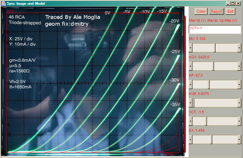
Dmitry kindly produced a very accurate model for the 46 (and also shown clearly that I’m a still a rookie at this things ):

And here is the equivalent Spice model:

Using a simple circuit in LTspice we can test the model and trace the anode characteristic curves:

And the curves can be easily generated:


Note that grid voltage starts at 0V in -10V steps.


Improving the 01a DHT preamplifier stage

After playing with DHT preamps (26, 71a, 4P1L, 46), I ended up staying with a CX301a version of it. I liked its warm sound and tone so I decided to stay with it. It’s been over 2 months so far that I haven’t returned to my precious 26 preamp (I will probably revisit my 26 preamp based on latest updates from Andy Evans).As I’m working on a version of the 4-65a SE amp by Michael Koster, I started investigating options and ways of improving the 01a as will be the first valve of my amplifier.

Using curves plot with my curve tracer and Dmitry’s composite model, I got a very well matched spice model for the 01a.

I modelled in LTSpice two versions of the gyrator loaded preamp with filament bias and Rod Coleman’s superb filament regulator:

1) Version 1: Using Anatoly’s PNP-FET Gyrator

2) Version 2: using classic cascoded-FET gyrator with mu-follower output.

Interesting results came out of this first simulation test. I think I haven’t managed to optimise (again) Anatoly’s gyrator despite have managed to keep good VDS (38V) to keep the CoSS low. I get slightly worse THD (0.03% versus 0.016%) compared to the MOSFET version.

Looking at output impedance, version 1 has 10K @1kHz whereas the version 2 can get as low as 734 ohms but impedance raises significantly at low frequencies (70k version 1 versus 80k version 2). This can be reflected in the frequency response where version 1 performs better than version 2.

Output impedance (Version 1)

Output impedance (Version 2)

At high frequency both preamps perform very well up to 1MHz despite version 2 performing slightly better.

Frequency response (version 1)
Frequency response (version 2)