Have you ever built a HT power supply for your amplifier, turned it on and experienced some smoke? Well if you haven’t you either have been lucky or too meticulous when testing. Either way, there is always good to have a safe mechanism to test our power supplies, amplifier, etc. Some devices are too precious to take any risk when doing the first tests.
A Variac is a perfect device for your tests. Is actually an autotransformer for the mains. As it’s an autotransformer there is only one winding therefore there will be no isolation between mains and the output. There are many Variacs in the market. As I wanted to add current and voltage meters (see below), I decided to build my own. There are some cost benefits as well and you can build this circuit very easily.
My choice was the Indian Ravistat 2F-1: an open type, single-phase variable transformer, rated at 240V@2A. This variac gives a continuously variable alternating current (a.c.) output voltage, has a solid construction, high efficiency/excellent regulation and no waveform distortion with smooth linear output & overload capacity.
 A 2A Variac will provide at least 1.8A @ 240V (432W). This is more that what I need for my testing purposes. You may want to go for a higher power version depending on your specific requirements.
The idea of adding the current meter is very simple, but effective. The current meter will give you an early warning that something may be going wrong if the current surge is more than expected. In that case you can stop and dial down the voltage to avoid a problem.
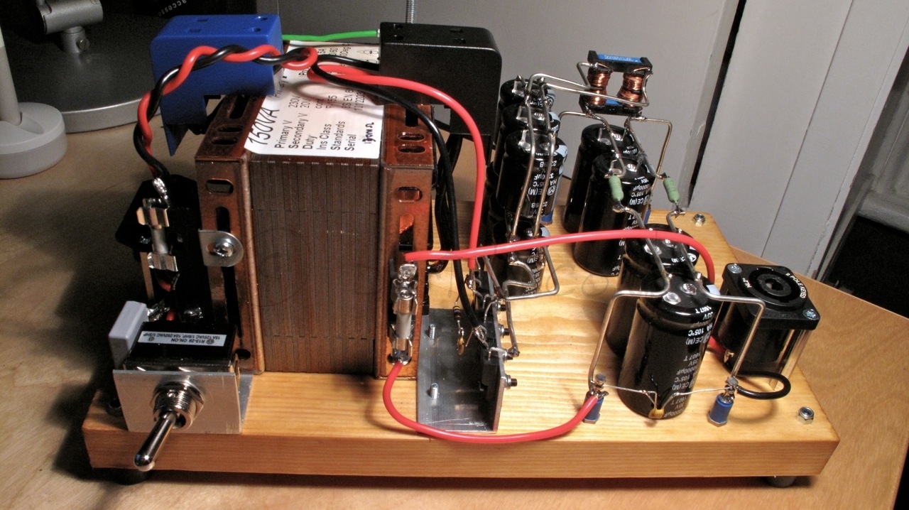
I bought a pair of cheap Chinese AC meters. I built the bench Variac using the remainder of a floor plank which I applied a cover of button polish and clear wax. Using aluminium and standoffs I placed the heavy Variac, added the switch and mains connectors. I have binding posts for tests as well as a proper AC outlet:


Now, it’s time to progress with the amp building and start using this device when testing!
Cheers,
Ale

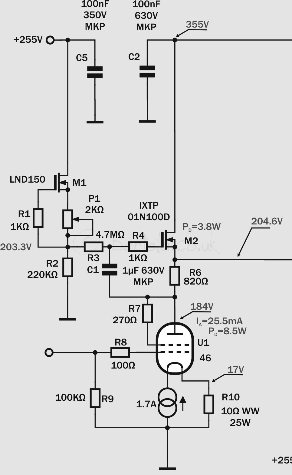
 The performance is very good. I just picked up a random 46 from my stock and biased it at 204V (which is the operating point in my design) achieving less than 0.05% at 10Vrms. Need to re-run this test to see how will perform at 70Vrms:


