
Introduction
A phono stage is probably one of the most challenging circuits to build in audio. Clearly not for beginners, many make the mistake in adventuring in building one. There are several designs which are simple, albeit many are poor ones. In addition to the challenges related to high-gain and very low noise design, audio enthusiasts really overlook the fact that you need to be able to measure and adjust the RIAA curve for a successful phono stage build. This means that you need an IRIAA signal source and also an accurate LCR bridge to adjust the network. I personally built a great IRIAA box and procured several LCR meters including this one as part of my learning journey of phono stages.
I’m not looking to discourage people here, I’m just warning beginners simply because we are all tempted to build a phono stage at some point. If you’re looking to learn about phono stages, Morgan Jones has devoted a nice set of chapters in his book. Highly recommended to make a start here.
When I embarked on the phono project time ago, I decided to build a solid state one as they do have several advantages against the valves in this particular application. I built a fantastic stage using a JFET input folded cascode, classic passive network and final amplification stage with an operational amplifier (OPA604). This phono stage sounds beautiful and it was very well received in the London Hi-Fi circle meetings by several members.
Since I’m a valve’s man, I couldn’t resist to go back to my roots and explore the RIAA stage topologies and options. The LCR network has had a lot of attention in the last years, and many have built great stages around LCR inductors provided from Dave Slagle and other sources. I had personally the opportunity to listen to one stage with LCR and was particularly interested with the sound of it.
LCR stages are very difficult to implement. It’s not just about the inductors involved, but mainly on the stress put on the driver stage. A typical 600Ω LCR network needs a source impedance of 600Ω (or the network needs to be terminated with the same impedance). Driving a 600Ω load is not easy for a valve, specially when expected distortion should be extremely low. This reduces the options available for the driver. Typically a cathode follower is used which, if we use a high transconductance valve like 6C45P, the output impedance is less than 50Ω.
The LCR network
There are several variations out there on the 600Ω LCR network. The following diagram shows a typical stage driven by an IRIAA source and terminated in a 100KΩ load via a coupling capacitor (C5):
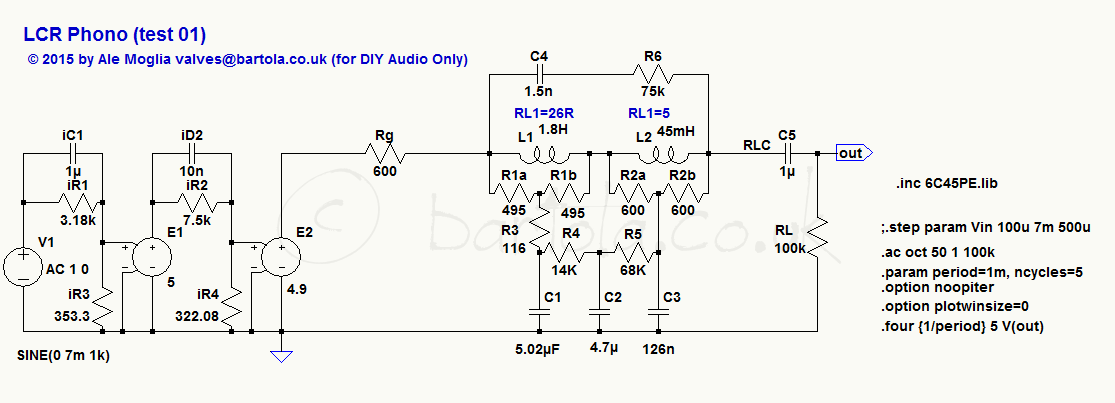 The source resistance is added as Rg to match the 600Ω requirement for the network performance. R6 and C4 provides HF compensation to flat out the frequency response beyond 10kHz. I’d expect these values to be AOT given the interaction with the leakage capacitances from L1 and L2. Note that in this LCR network the capacitances are big. Not ideal for us who don’t like big capacitors around the signal path. Here is the response of this network:

The network can be adjusted to +/- 0.2dB or better. You will need an LCR bridge to measure and trim the capacitors and inductors with several taps like the ones provided by Dave Slagle are great to achieve tighter compliance to the RIAA curve.
For an AC-coupled stage, the presence of C5 is bad news to our ears. Having a big capacitor is not ideal here. The constrain is on the load (RL) which generally is the grid leakage resistor of the second/third stage in the phono stage. We will deal with this later.
A 600Ω LCR network is a tough load. For this reason some people have actually tried with success higher LCR networks like 6K and even 11K. A 6K LCR network is a more manageable load and for a cathode follower, a nice load to drive. How does it look in real life? Well, scaling the network 10 times you get the following:
 Not only the load is good for the driver, the capacitances (C1 to C3) have a more reasonable value to minimise their sonic impact. The challenge is that L1 is now 18H which means that higher leakage capacitance will be playing here. However, the results reported by Dave Slagle and others are very encouraging. The response is shown below:
 The 20dB attenuation has to be taken into account when designing the phono stage.
The typical driver stages are:
- Cathode follower: a resistor in series to the output of the follower can be added to match the source driving impedance.This is an effective and good solution, however it needs an extra valve
- Transformer coupling: a step-down transformer provides lower impedance. Using high gain / transconductance valves like 6J52p, C3g, D3a, 6C45P presents a challenge to the transformer design and this is more expensive
- Pentode stage: a first pentode stage can deal with the Miller capacitance challenge to the cartridge whilst providing good gain. Not every pentode works here as they are noisier than triodes here but some are good. A pentode stage like E180F or the previous mentioned can also be connected with a series resistance to match the load of the LCR network. The challenge is that to provide a low output impedance the anode resistor needs to be low in value which impacts the gain of the stage. Some good designs are out there using pentodes and are interesting to look into.
In part 2 of this blog entry I will show some design options for an LCR phono stage (I need to find time to write this between changing nappies)
Cheers
Ale
Hello!
I could convince Brian Sowter to manufacture LCR inductors with higher internal impedance and wrote a small white paper about how to choose component values and measuring the results.
Here it is:
http://www.sowter.co.uk/pdf/LCR-RIAA%20Ahlswede.pdf
Best regards!
Bernd
Excellent article Bernd! I hope this encourages others to build their own LCR stage.
Cheers
Ale