
Finished the 4-65a filament regulators. Filament noise is only 1.5 mVrms at full load (3.5A):
Tag: 4-65a SE amplifier
4-65a SE Amp: 46 Driver Gyrator
A day of PCB etching
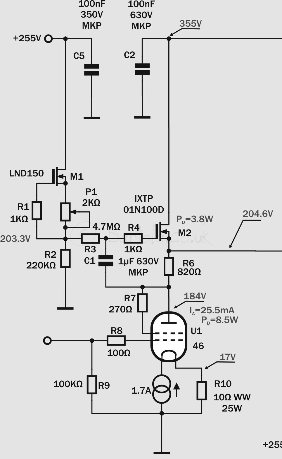
 After a lot of work today in designing many PCBs, I finally got a pair of mu-follower MOSFET gyrators for the 46 driver stage. The driver has to provide very low impedance to operate the 4-65a output valve in class A2. The gyrator in mu-follower configuration will enable the right bias point as the amplifier is DC coupled as well as maximum signal (and current in A2) with minimum distortion.
Many don’t like sand at all in their amplifiers. I have a lot of experience with gyrators and CCS loads in pre-amps and drivers as well. I have to say that with MOSFETs gyrators the sound is really nice. For an A2 driver, not many options are available and the gyrator is a great choice for this job.
I built two PCBs (one per channel) and the circuit is the classic depletion-mode MOSFET gyrator based on the high-voltage IXTP01N100D. I guess that a DN2540 should work as well here but I’ve been saving the IXYS for this occasion. The reference voltage for the anode bias point is provided by the CCS formed by M1 (LND150) which provides a higher impedance in AC improving the frequency response of the gyrator.
 The 46 is operating in triode-mode and filament bias with a Rod Coleman filament regulator. R6 is approximately 1/gm and output voltage is set by P1 to achieve the 4-65a bias point as the amplifier has stacked power supplies given coupling is DC, so no capacitors in the path to the grid.
Next: some tests on these gyrators and the filament boards…
4-65a SE Amp: 46 Driver Raw Supply
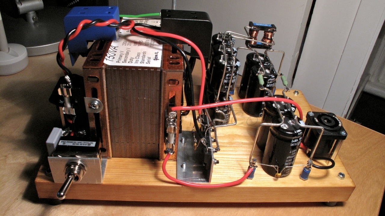
One more filament raw supply completed today: the 46 driver in filament bias. This driver stage requires 26V @ 1.7A due to the filament bias requirements. Yes, nearly 45W in the filament but will provide a fantastic driver stage with the 46 triode-strapped and filament bias to avoid any nasty capacitor in the signal path.
The power supply design is very simple and follows Rod Coleman’s recommendations for the DHT filament regulators. One drawback in this version, compared to the output stage raw supply, is that this will be pure capacitor filtering with no help of a choke to reduce the input current pulses.

The split-bobbin 150VA transformer provides sufficient current for the capacitor input filtering stage. The DSB10I45 (Schottky 45V/10A) bridge is also mounted on a “L” shape aluminium piece.
The capacitor arrays are soldered to a thick bare wire which provides structure and simplifies connections between components: 
I was initially concerned that without shielding the high-current pulses may introduce some noise in the output as F2 fuse is mounted on the transformer frame so the wire is routed back and forward to that point. Reality is that the hum level is very low. I measured 16.4mV peak-to-peak at full load.
4-65a filament supply mono block
Today made more progress as managed to build one of the 4-65a raw filament supplies. They weigh a ton so decided to build monoblocks for all filament power supplies as well as the main amp.


The power supply is built on a piece of wood. This is a fast method for breadboarding the amp which provides fantastic results. I’m using PTFE sleeved wire for the first time. This is rated 600V and 10A, sufficient for the requirements here.
The common-mode choke is built under the capacitor arrays to reduce wire length and optimise space use.
The choke and 200VA transformers are bolted directly to the board.

The Schottky rectifier bridge is mounted on an 4mm alumminium angle which is primarily used as heat sink and also the solid structure helps to mount the first capacitor array very close to the bridge.
Tested the supply with a dummy load of 3R3 50W. Ripple is only 53mVpp which will be dramatically reduced by the Rod Coleman filament regulator.
Edit (28th December 2012)
Just made a minor adjustment of the output voltage by the addition of R1 and R2 and fuse F1 was increased to 2A to avoid blowing it at full load when switched on:

4-65a filament supply
One of the good things about Christmas is that I always managed to get some proper time for working on my projects. This year is devoted to my belated project: 4-65A SE amplifier. We bid farewell to our family guests so had this evening a bit of time to start preparing the filament raw supply for the 4-65A.
This will be a heavyweight amplifier. Too much iron, but 100% DHT and no capacitor in the signal path, a promising design.
A couple of hours were sufficient to prepare some of the key components: a pair of common-mode chokes winded on ferrite rings, capacitor arrays and a Schottky bridge mounted on an aluminium sink:

The raw filament supply circuit follows the standard design recommended by Rod Coleman to use the filament regulator boards. I managed to get a nice pair of 10mH@3.5A chokes made by JMS transformers which is the same company that provides the custom-made split bobbin transformers:

The 10mH choke will help reducing the current pulses and the input capacitance, which is less than 3mF. This circuit will provide 12V @ 3.5A with a ripple current of 31mV peak to peak maximum.
4-65a EIMAC
4-65a EIMAC NOS DHT
Just got a couple of NOS EIMAC which I will be using in my SE design

 So did some test on distortion, transconductance and driving them to +22.22dBu output to check the quality of these two ones.
I used similar test rig as before. At some point will be able to get a proper filament supply for this valve, but for the time being I will continue to use the hum pot and the big electrolytic cap across my old bench power supply which can gently provide the 3.5A for the hungry filaments!
I tested them at the limit of my CCS and bench HT supply which at the moment cannot provide more than 360V @ 100mA.
Transconductance is in the region of 3,800 – 4,000 μmhos.
So biasing the valve at -2.5V and over 90mA of anode current, the harmonic profile looks like this:

Both EIMAC measured about 0.12% THD.