4P1L model improved

 Improving the DHT model in A2

After playing for some time with the uTracer, I found that the tracer wasn’t measuring accurately A2 curves. Ronald clearly advised me (as explained on his site) that uTracer wasn’t designed for this purpose although there was a great trick to use the screen driver to generate the A2 curves and also measure grid current. Measuring grid current is key in A2 mode so a better grid current model can be derived to better simulate the non-linear and low impedance behavior of the grid in positive bias.

My incarnation of the uTracer is not neat. I’m using my existing analogue curve tracer. As shown in the pictures below, my current tracer have a plethora of sockets and just adding right jumper cables for anode, cathode, screen and grid connectors will still give me the flexibility I had with my analogue tracer

The process of generating the A2 curves (and SPICE model) starts by plotting the normal curves. The uTracer is great for this. Then you have to overlay the A2 curves in Excel (or whatever tool you prefer) to combine both set of curves.

Continue reading “4P1L model improved”

4P1L: Tracing A2 curves (first test)

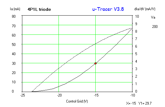
Just finished the digital tracer project uTracer V3. Did some further tests this morning, now with my favourite DHT: 4P1L.

Started with a well known bias point for triode-strapped operation:

4P1L Va=200V Continue reading “4P1L: Tracing A2 curves (first test)”

uTracer up and running

After a stupid mistake which blew the PIC, I finished today my version of the uTracer. A quick trace of an CX-226 RCA Radiotron can be seen below. This is an incredible digital tester. I need to test it properly and do some comparisons against my analogue tracer, but as everyone would expect,the digital tracer has superior capabilities in terms of data manipulation and representation.

Highly recommended. Ronald provides a sterling service and specially when I damaged the PIC and send me a replacement at no cost!

More to come shortly…cx226 RCA test

Improving the valve curve tracer (part 3)

Didn’t take as long as I thought to build the new anode current sensor for the valve curve tracer. A simple PCB was used to solder directly the components for a quick solution. Here is how it looks:

DPP_0008


valve-tracer-sense02

I tested this new circuit with some valves from high transconductance to low current ones. The current amplifier works like a charm. I used a CCS first to calibrate the x10 output and found a great linearity from 1mA up to 100mA. Currently I used my bench power supply to test this but I’m planning to do some major surgery to the tracer and include this sensor inside the main chassis.

With a dual 15V supply the AD8479 can work with up to 600V in common mode. This is perfect for my tracer and can be used to sense anode and screen currents.


Improving the valve curve tracer (part 2)

After some feedback from the DIYaudio forum clearly the INA122 was a killer in this application as no differential signal was used at the output stage. Despite having an INA122 around, I looked at an alternative option with a good op amp I had at hand. The LM833 is a dual low noise op-amp that can do the trick here:

valve-tracer-sense02

Continue reading “Improving the valve curve tracer (part 2)”

307a with schade feedback (Part II)

Some time ago I traced the 307a that kindly Vegard Winge sent me from Norway. As suggested by Vegard, I re-traced them with lower screen voltage and increased feedback to improve the linearity of the 307a in this mode.

307a schade testThe modification to the curve tracer is simple. A simple resistor divider (R1, R2) provides the feedback to the grid. The grid driver provides a constant impedance so works fine. With a potentiometer you can adjust the feedback ratio and look at the impact on the curves. Very handy!

With 15.5% feedback and 125V screen voltage I got the best curves as shown below:
307a schade 15.5FB 125V

Nice to see the anode resistance coming down to 1kΩ.I tried matching a triode model to these curves with a good result

Continue reading “307a with schade feedback (Part II)”

4P1L triode SPICE model

After playing for some time with Dmitry’s great DHT composite triode models, I looked at refining the model by matching my own set of curves of the 4P1L in triode-mode. Here is my take on it:

4P1L Triode Model Continue reading “4P1L triode SPICE model”

2e24 DHT

IMG_0369 SMALL It was suggested to me recently by Piotr to explore the 2e24 after looking at the 2e22. This small directly heated pentode have about 10-12W of anode dissipation depending how it’s wired. I suspected this DHT in triode mode will have a high anode resistance so as soon as I managed to get hold of a sample, I submitted it to the mercy of my curve tracer:

Continue reading “2e24 DHT”

A high-mu DHT (841/VT-51)

IMG_0332Thomas Mayer presented in his blog a great article about this DHT. A very interesting valve for preamps given its unusual high-mu (circa 30). It could be used in filament bias despite its high filament current needs (see the curves). Ideally choke loaded or IT transformer coupled, I suspect it could perform well with a mu-follower gyrator to provide a low output impedance given its high Ra (for those who are not uncomfortable with some sand assistance 🙂 )

Here are the curves:

VT-51-841SMALL

I found Ra to be around 20-25KΩ, instead of the higher value highlighted by Thomas.

Here is the SPICE model:Triode 841-Composite

VT-51 841 triode modelWhich produces a nice set of curves extending to the positive grid current region suggesting an interesting use in A2:

841 Curves

864 / VT-24 DHT curves

IMG_0336This is one of the other great DHTs I received from Vegard Winge for tracing.

Here are the curves and the SPICE model: 864 DHT Composite

864 SMALL 864 SPICE model


The SPICE composite model based on Dmitry’s:

**** 864 VT-24 DHT Composite ******************************************
* Created on 03/16/2013 19:30 using paint_kit.jar 
* www.bartola.co.uk/valves
* Curves image file: 864 SMALL.jpg
* Data source link: 864 SMALL.jpg
* Created by Ale Moglia valves@bartola.co.uk
*----------------------------------------------------------------------------------
.SUBCKT TRIODE_864-Composite 1 2 3 4 ; Plate Grid K1 K2
+ PARAMS: CCG=2.3P CGP=5.3P CCP=1.3P 
+ MU=7.14 KG1=13560 KP=98 
+ KVB=1.88 VCT=-0.07 EX=1.41 RGI=2000
* Vp_MAX=200 Ip_MAX=0.008 
* Vg_step=2 Vg_start=0 Vg_count=11
* END PARAMS -----------------------------------------------------------------------
* cathode resistor is 4.4 ohm, the pins K1 and K2 are 1.1 ohms from the ends of it
RFIL_LEFT 3 31 1.1
RFIL_RIGHT 4 41 1.1
RFIL_MIDDLE 31 41 2.2
E11 32 0 VALUE={V(1,31)/KP*LOG(1+EXP(KP*(1/MU+V(2,31)/SQRT(KVB+V(1,31)*V(1,31)))))}
E12 42 0 VALUE={V(1,41)/KP*LOG(1+EXP(KP*(1/MU+V(2,41)/SQRT(KVB+V(1,41)*V(1,41)))))}
RE11 32 0 1G
RE12 42 0 1G
G11 1 31 VALUE={(PWR(V(32),EX)+PWRS(V(32),EX))/(2*KG1)}
G12 1 41 VALUE={(PWR(V(42),EX)+PWRS(V(42),EX))/(2*KG1)}
RCP1 1 3 1G
RCP2 1 4 1G
C1 2 3 {CCG} ; CATHODE-GRID
C2 2 1 {CGP} ; GRID=PLATE
C3 1 3 {CCP} ; CATHODE-PLATE
D3 5 3 DX ; FOR GRID CURRENT
D4 6 4 DX ; FOR GRID CURRENT
RG1 2 5 {RGI} ; FOR GRID CURRENT
RG2 2 6 {RGI} ; FOR GRID CURRENT
.MODEL DX D(IS=1N RS=1 CJO=10PF TT=1N)
.ENDS
*$


Hope this is useful…

Ale