Thought it was going to be an easy task as I’ve done it before many times and building a Shunt regulator seems to be not the challenging part of this amplifier build. We all know that life brings surprises and specially when we are not expecting them. My 4-65a SE amplifier requires a very stable DC as part of the DC-coupling design. The Salas Shunt Regulator version 2 (a.k.a. SSHV2) is a good choice for this task.
New pass FET
Fitting new pass MOSFET and CCS
Salas SSHV2 shunt regulator
After building it very quickly I struggled to get it to work. To cut a long story short which involved some IRF840, PNP and JFET replacements, I discovered that the stabilising RC wasn’t connected as the 330nF MKP capacitor was not properly soldered to the right holes. The PCB has multiple holes to accomodate capacitor sizes, however only the top two correspond to one capacitor pin and the remaining bottom ones are for the other. My logic of placing the capacitor in the centre clearly didn’t work and the capacitor was disconnected in the end. Finally, when hooking the regulator to the raw supply and switching it on, the whole thing produced the unwanted smoke particular of sand devices getting blasted. What happened? The maximum input voltage to the regulator evidently exceeded the CCS voltage and the top FET (M1) blowed away and therefore the regulator cascode CCS (J1) and the pass FET (M3) as well. My PCB was already suffering from multiple solder work and was reaching to its usable life. I looked at using HV parts as hand to increase the robustness of the regulator. The pass-FET was replaced by a 1kV part (STE5NK100Z) and the Mosfet CCS DN2540 pair for an IXTP01N100D which is also 1kV part:
All worked well until I realised that the differences between DN2540 and 01N100D’s VGS(th) and gm made the CCS maximum to be limited to about 40mA given the test point resistor value. As M2 can be a simple DN2540, I replaced it back and all worked well to get 60mA and deliver about 280V @ 40mA rock-solid!
I could easily say that by now I’m tired of building power supplies. Yes, I’m and fundamentally can’t see the day when I get to fire up this amplifier.
Filament supplies and three stacked power supplies is the price I’m paying to get a completely cap-less and DC coupled A2 amplifier. I guess that my analysis once completed will be made with full perspective of every single implication of this amp: iron, heat and weight. Yes sir, this is a heavy-weight challenger.
I guess that this specific HT power supply design is quite flexible as could be easily reused in many of the projects I have in mind, which unfortunately keep growing.
Good thing is though, I can make these supplies pretty quickly, but don’t do this at home ok? There is serious HT involved. I don’t have pets or kids (but do have a wife) and these supplies should be hidden and away from any poking curious finger.
The final design is similar as the one used before. Could be adapted to choke input, but with the components I had at hand, this supply is very well filtered. It provides only 15mV ripple noise which at 330V is a lovely noise floor around -87dB:
The mains transformers are Weiss (excellent quality) which has screened windings. Instead of having a full Graetz valve rectifier and waste more heat (and use more damper valves), the rectifier is hybrid using a pair of UF4007. Capacitors are oil and polyester ones for the output HF decoupling on each rail. Each channel will feed a Salas SSHV2 shunt regulator which will provide the stable DC reference for the 46 driver stage and bias point for the output 4-65a stage.
Bad news is that, there is one supply left to be built before I can test at least one channel!
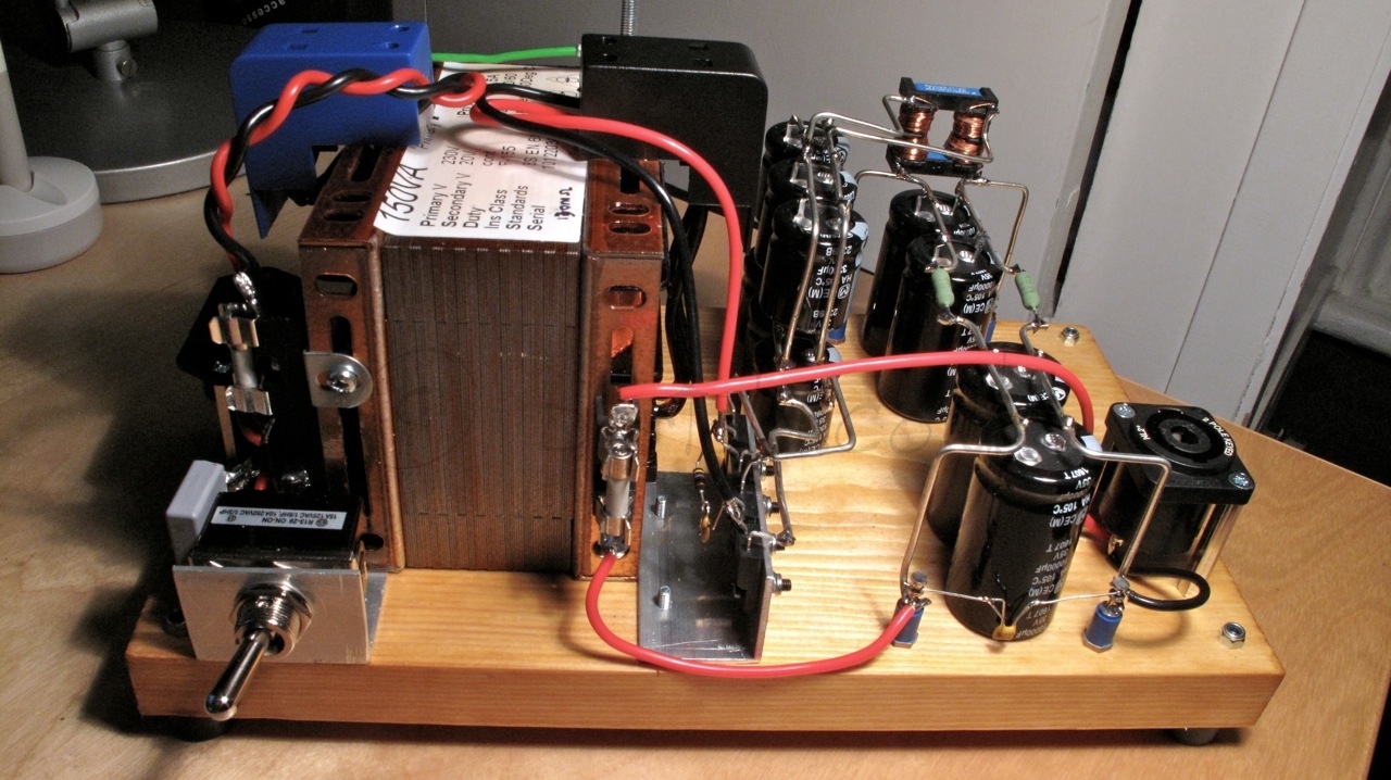
One more filament raw supply completed today: the 46 driver in filament bias. This driver stage requires 26V @ 1.7A due to the filament bias requirements. Yes, nearly 45W in the filament but will provide a fantastic driver stage with the 46 triode-strapped and filament bias to avoid any nasty capacitor in the signal path.
The power supply design is very simple and follows Rod Coleman’s recommendations for the DHT filament regulators. One drawback in this version, compared to the output stage raw supply, is that this will be pure capacitor filtering with no help of a choke to reduce the input current pulses.
The split-bobbin 150VA transformer provides sufficient current for the capacitor input filtering stage. The DSB10I45 (Schottky 45V/10A) bridge is also mounted on a “L” shape aluminium piece.
The capacitor arrays are soldered to a thick bare wire which provides structure and simplifies connections between components:
I was initially concerned that without shielding the high-current pulses may introduce some noise in the output as F2 fuse is mounted on the transformer frame so the wire is routed back and forward to that point. Reality is that the hum level is very low. I measured 16.4mV peak-to-peak at full load.
Have you ever built a HT power supply for your amplifier, turned it on and experienced some smoke? Well if you haven’t you either have been lucky or too meticulous when testing. Either way, there is always good to have a safe mechanism to test our power supplies, amplifier, etc. Some devices are too precious to take any risk when doing the first tests.
A Variac is a perfect device for your tests. Is actually an autotransformer for the mains. As it’s an autotransformer there is only one winding therefore there will be no isolation between mains and the output. There are many Variacs in the market. As I wanted to add current and voltage meters (see below), I decided to build my own. There are some cost benefits as well and you can build this circuit very easily.
My choice was the Indian Ravistat 2F-1: an open type, single-phase variable transformer, rated at 240V@2A. This variac gives a continuously variable alternating current (a.c.) output voltage, has a solid construction, high efficiency/excellent regulation and no waveform distortion with smooth linear output & overload capacity.
A 2A Variac will provide at least 1.8A @ 240V (432W). This is more that what I need for my testing purposes. You may want to go for a higher power version depending on your specific requirements.
The idea of adding the current meter is very simple, but effective. The current meter will give you an early warning that something may be going wrong if the current surge is more than expected. In that case you can stop and dial down the voltage to avoid a problem.
I bought a pair of cheap Chinese AC meters. I built the bench Variac using the remainder of a floor plank which I applied a cover of button polish and clear wax. Using aluminium and standoffs I placed the heavy Variac, added the switch and mains connectors. I have binding posts for tests as well as a proper AC outlet:
Now, it’s time to progress with the amp building and start using this device when testing!
After tedious work and proper testing, I managed to finish today the 600V feedback regulator. Previous version had to be tweaked as LF351 operational amplifier latched up. After a quick PCB hack, the LM358 was replaced instead with instant success. The supply can regulate from 0 to 600V and provide up to 100mA:
After being out of action for over a month due to visits, holidays and business travel, I finally got the opportunity to get my hands back on the 600V bench supply. I need to repair my valve tracer, but firstly need the bench supply back again. Otherwise won’t be able to do all tests I want to around my 814 DC-coupled SE amplifier and many driver stages I want to try on my workbench before moving to the next stage.
An improved design to avoid fireworks
Tired of my old HT (+600V) variable bench power supply to suffer collateral damage when accidentally shorted whilst testing transmitting valves for output stage (i.e. FQP3n80c MOSFET passive regulator blowing out), I decided firstly to decide a simple and yet effective valve stabiliser. As nothing comes for free, these were my design constrain factors:
Input raw supply is +620V @ 100mA
Filament secondary winding is 15V @1.5A
No additional secondary winding is available for a floating screen supply (e.g. pass valve is pentode)
Output voltage ideally should be 0-600V
So with the restriction of not using a pentode as pass valve, I looked out for candidates to match my requirements and instantly thought about GU-50 in triode-strapped mode. Yes, I know that UG2 limit is 250V, not 1,000V as anode max voltage. But, in triode strapped specs are not shown. As recently checked this with the 814 triode strapped, and seems to be ok UG2=Ua in triode mode. 7N7 also said this was ok and Morgan Jones previously tested this as well with similar valves.
So, question here initially was: could the GU-50 withstand 600V in triode mode or should I needed to look out for other options?
After asking for some help in DIYaudio forum to see what was the best option on this topology and the recommendation was to use the GU-50 in “right-handed mode”:
GU50 right-handed
In this mode GU-50 was able to provide the regulation required (or close to it) with minimum driving requirements (i.e. 0V to +15V)
First version of the passive regulator:
The MOSFET is in source follower mode to provide the necessary grid current, albeit not sure how much grid current the GU-50 needed in right-handed mode. So the value of R6 must be adjusted on test. In order to survive an output short, R6 needs to be in the order of 100K and 3 or 4W to avoid blowing up the 18V zener protecting the grid.
The circuit above is very interesting as the anode dissipation of the GU-50 is very handy for this setup and requirements. Is important to highlight that the circuit has no regulation, so if this is a requirement a different topology must be explored.
If we look at the sandy option here, then the following equivalent is comparable:
R2 and R3 are required to protect silicon from output short. Q1 provides current limitation with R6. This topology suffers from same issues related to regulation as previous circuit.
A big issue on the two circuits presented before is that the potentiometer is stressed at full raw HT supply. This is far from ideal and despite the specific power requirements of the pot, we also need to ensure that the part can withstand the voltages used.
A slight modification (requiring an additional LT supply) can solve this problem:
Now P1 is connected to 15V. The gain of the M2 stage is significant so stability of circuit above is an issue now.
So if we have already introduced an LT supply in the circuit, then is a better choice to look at a feedback regulator.
A more complex circuit indeed, but a more effective one. The op-amp provides regulation by sensing output from R7 and R8 divider and comparing it to the stable reference from the output of P1. R10, R9 and C1 limit the HF gain response of the op-amp. R12/C3 and the 10pF FKP2 Wilma cap across R7 optimise the HF response of the overall regulator. D1 will protect the op-amp input (specially if 10pF cap is fitted). R1 is an additional protection for M1. M1 requires a good sink if wider regulation is needed. When output voltage is low and high current is drawn, then M1 is bearing all the effort and will dissipate a lot of heat (just do the maths).
The raw supply stays the same, however the gyrator stage was optimised as shown below:
The MOSFET was changed for am 1000V TO220FP plastic package one which is better from an insulation perspective given voltages used in this circuit. R5 and R6 changed to 150K 3W ones to provide protection to the zener and M1 in case output is shorted.
Here is a quick test of a russian СГ2С (SG2S) 75V voltage valve regulator:
The CCS is a classic cascoded DN2540 MOSFET. A russian PIO capacitor is bypassing the regulator and the input impedance is the Pete Millet’s interface impedance. HT is a well regulated variable power supply.
When near maximum bias current is achieved (circa 30mA), the noise floor is surprisingly low: -85.5dB / 53uV.
Need to capture input of power supply at the CCS input 🙂
Edit: after measuring the power supply noise level and finding that is near -90dB, came up to the conclusion that the above noise level is the VR noise. Quite good for a simple (but effective) voltage regulator. Gary Pimms used this configuration many times on his designs…
Update
Upon request from Vyacheslav, here is the noise analysis for different current points:
As you can see it’s very linear. There is a 4dB difference between 5mA and 40mA.
Also tested ripple attenuation using a poor-regulated HT power supply. Here are the interesting results:
It took me probably half an hour to build this brilliant shunt regulator. I waited for a long time until picked up this board and stuffed all components. I will use it in my next generation of DHT preamps.
Output ripple is below 5mV, can’t even measure it given the noise in my workbench. The test gig included my variable power supply (600V) feeding the shunt regulator which was set for 40mA. output load is three 3K3 power resistor clads (50W each).
I adjusted the regulator to provide about 160V, so current is about 16mA. Interesting to seer the harmonic profile to have a higher peak at 200Hz compared to the 100Hz harmonic….


 All worked well until I realised that the differences between DN2540 and 01N100D’s VGS(th) and gm made the CCS maximum to be limited to about 40mA given the test point resistor value. As M2 can be a simple DN2540, I replaced it back and all worked well to get 60mA and deliver about 280V @ 40mA rock-solid!


