4-65a SE Amp: testing it finally!

The much-awaited moment finally arrived. After yesterday’s driver tests, I did a lot of work this morning to assemble cables and test the output stage. What I clearly know now is that I won’t be needing any heating this winter! What on earth was on my mind when I decided to build this amp? God only knows…

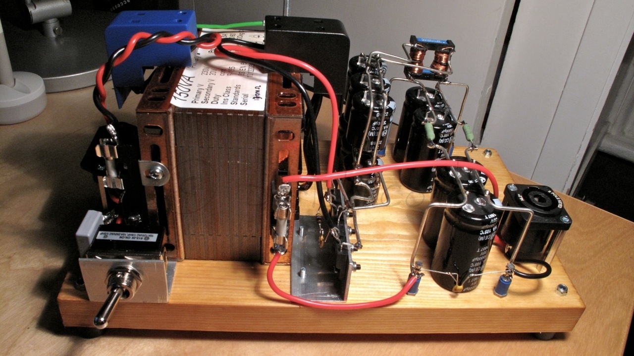
Here are some pictures of the first tests in the workshop and then when I hooked it up to my system downstairs in the sitting room:

I did a quick measurement of the output THD without burning in the 4-65a or the amp. The operating point is not optimised but clearly shows a nice picture. First of all, the amp is absolutely quiet. The Rod Coleman regulators plus the extensive filtering on all supplies (LCLC and CLCLC) make this the quietest amp I’ve ever made! The distortion is higher than predicted. With the valves at 100mA/540V and with a non-inductive resistor load of 10Ω, the THD is about 2.7% for nearly 6W of pure class A power. Only 4% of the harmonic content is H3 and with a nice H2 component. The footprint of an SE amp is clearly on this amp.

4-65a SE Power test 5.6W test1

Hooked it downstairs and after a lot of wiring I finally got to play some good records on this amp. I used my 26 DHT preamp. First record to be played was “a love supreme” (John Coltrane). Here are my impressions so far:

  • I’m surprised with the bass. It is powerful and not something I was used to in a single ended amp
  • Definitely needs some burn-in time. The amp improved after 1 hour of use
  • It’s loud! You can get 10W easily in class A2. Very loud for my room!
  • The tone is warm and very sweet. you get the sound of the DHT clearly
  • Dynamics are its forte. This amp responds very well to them

Some more pictures:

Now is time for proper listening after so much work. A real accomplishment and I’m feeling very proud. The amp fits within my cabinet so wife is happy 🙂


4-65a SE Amp: Building process (Part 2)

Further progress today: more cabling done for the SSHV2 boards and A2 current raw supplies for the 46 driver gyrators….


4-65a SE Amp building process

Some drilling and mounting work done this morning on the 4-65a SE amp breadboard:

During the afternoon, I managed to wire a filament supply for one channel 46 driver. Tested and working ok, now can move to the next one:

4-65a SE Amplifier: testing filament regulators

The Rod Coleman Filament Regulators were already tested in the New Year. It seems a long time indeed. Here is a selection of pictures after fitting the regulators in their heat-sinks and doing a final test before assembly:

4-65a SE Amp: Shunt regulator

Thought it was going to be an easy task as I’ve done it before many times and building a Shunt regulator seems to be not the challenging part of this amplifier build. We all know that life brings surprises and specially when we are not expecting them. My 4-65a SE amplifier requires a very stable DC as part of the DC-coupling design. The Salas Shunt Regulator version 2 (a.k.a. SSHV2) is a good choice for this task.

After building it very quickly I struggled to get it to work. To cut a long story short which involved some IRF840, PNP and JFET replacements, I discovered that the stabilising RC wasn’t connected as the 330nF MKP capacitor was not properly soldered to the right holes. The PCB has multiple holes to accomodate capacitor sizes, however only the top two correspond to one capacitor pin and the remaining bottom ones are for the other. My logic of placing the capacitor in the centre clearly didn’t work and the capacitor was disconnected in the end. Finally, when hooking the regulator to the raw supply and switching it on, the whole thing produced the unwanted smoke particular of sand devices getting blasted. What happened? The maximum input voltage to the regulator evidently exceeded the CCS voltage and the top FET (M1) blowed away and therefore the regulator cascode CCS (J1) and the pass FET (M3) as well.  My PCB was already suffering from multiple solder work and was reaching to its usable life. I looked at using HV parts as hand to increase the robustness of the regulator. The pass-FET was replaced by a 1kV part (STE5NK100Z) and the Mosfet CCS DN2540 pair for an IXTP01N100D which is also 1kV part:

4d3c217103c69e625831992a99131b35All worked well until I realised that the differences between DN2540 and 01N100D’s VGS(th) and gm made the CCS maximum to be limited to about 40mA given the test point resistor value. As M2 can be a simple DN2540, I replaced it back and all worked well to get 60mA and deliver about 280V @ 40mA rock-solid!


4-65a SE Amp: HV3 supply

20130209-162653.jpgBuilding the HV3 (+330V Supply)

I could easily say that by now I’m tired of building power supplies. Yes, I’m and fundamentally can’t see the day when I get to fire up this amplifier.

Filament supplies and three stacked power supplies is the price I’m paying to get a completely cap-less and DC coupled A2 amplifier. I guess that my analysis once completed will be made with full perspective of every single implication of this amp: iron, heat and weight. Yes sir, this is a heavy-weight challenger.

20130209-162704.jpg I guess that this specific HT power supply design is quite flexible as could be easily reused in many of the projects I have in mind, which unfortunately keep growing.

Good thing is though, I can make these supplies pretty quickly, but don’t do this at home ok? There is serious HT involved. I don’t have pets or kids (but do have a wife) and these supplies should be hidden and away from any poking curious finger.

The final design is similar as the one used before. Could be adapted to choke input, but with the components I had at hand, this supply is very well filtered. It provides only 15mV ripple noise which at 330V is a lovely noise floor around -87dB:

4-65a SE HV3 330V Supply Version 1.0The mains transformers are Weiss (excellent quality) which has screened windings. Instead of having a full Graetz valve rectifier and waste more heat (and use more damper valves), the rectifier is hybrid using a pair of UF4007. Capacitors are oil and polyester ones for the output HF decoupling on each rail. Each channel will feed a Salas SSHV2 shunt regulator which will provide the stable DC reference for the 46 driver stage and bias point for the output 4-65a stage.

Bad news is that, there is one supply left to be built before I can test at least one channel!


4-65a SE Amp: testing the 600V raw supply

Burning the 6D22S damper valves20130120-190106.jpg

After a failed initial test which caused the silicon and the damping series resistor of the hybrid bridge to blow up due to a gassy NOS 6D22S, I burned in the valves for 30min and tested the supply with a dummy load.

Some few changes to the supply design included the replacement of the HV diodes with a series pair of 1200V@5A fast diodes. The filaments were referenced to cathode (+B) instead of ground to minimise Vhk and a snubber network formed of a pair of 100nF LCR 1.5kV capacitors across the input choke were added.

Supply under test

This is a hefty supply: massively heavy. The heaviest piece of iron I have built so far. Anyway, great decision to build this amp in a modular fashion, otherwise I would have need some mechanical aid for moving the stuff around and clearly my wife would have kicked me out of the house (she hasn’t seen this yet so the latter is yet to happen).

20130120-190032.jpg

The load resistor is a pair of 3k3 50W aluminium clad ones bolted to an aluminium piece which at the same time is held by a vice (thanks Rod for the suggestion). This provides sufficient mass and heat dissipation capacity (need about 120W).

Initial tests were great, need to do some further ones.

here is the diagram so far:

Update 9th Feb 2013: Minor updates including rightsizing of the mains fuse and removal of earth switch as this supply will be used in floating mode
4-65a 600v supply

4-65a SE Amp: 46 Driver Raw Supply

One more filament raw supply completed today: the 46 driver in filament bias. This driver stage requires 26V @ 1.7A due to the filament bias requirements. Yes, nearly 45W in the filament but will provide a fantastic driver stage with the 46 triode-strapped and filament bias to avoid any nasty capacitor in the signal path.

The power supply design is very simple and follows Rod Coleman’s recommendations for the DHT filament regulators. One drawback in this version, compared to the output stage raw supply, is that this will be pure capacitor filtering with no help of a choke to reduce the input current pulses.

4-65a 46 driver filament raw


The split-bobbin 150VA transformer provides sufficient current for the capacitor input filtering stage. The DSB10I45 (Schottky 45V/10A) bridge is also mounted on a “L” shape aluminium piece.IMG_3591

The capacitor arrays are soldered to a thick bare wire which provides structure and simplifies connections between components: IMG_3592

I was initially concerned that without shielding the high-current pulses may introduce some noise in the output as F2 fuse is mounted on the transformer frame so the wire is routed back and forward to that point. Reality is that the hum level is very low. I measured 16.4mV peak-to-peak at full load.