Just finished the digital tracer project uTracer V3. Did some further tests this morning, now with my favourite DHT: 4P1L.
Started with a well known bias point for triode-strapped operation:
All about electronic valves and hi-fi

Just finished the digital tracer project uTracer V3. Did some further tests this morning, now with my favourite DHT: 4P1L.
Started with a well known bias point for triode-strapped operation:
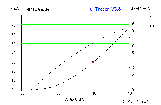
After playing for some time with Dmitry’s great DHT composite triode models, I looked at refining the model by matching my own set of curves of the 4P1L in triode-mode. Here is my take on it:
Last week I looked at optimising the 45 loadline in A2. Clearly we shouldn’t be attempting to get more than 2W from this valve without a significant level of distortion. However, having about of 3W would be attractive for the transient response of this amp.
So how will this circuit perform in a simulation? Let’s see what the spice results are:
 The THD is significantly better due to the harmonic cancellation between the two stages. The driver distortion is 0.3% at full tilt (150vpp) and this could be improved. I guess the 6e5p could do better, but interesting to see how the cancellation of harmonics may play around. The new operating point and the stacked supplies will demand different MOSFET parts of 1kV for sure…
Dmitry Nizh kindly worked out the 4P1L triode SPICE model using his great tool:

Here is Dimtry’s model:
** 4P1L_TRIODE ************************************************************
* Created on Mon Jan 07 07:31:48 PST 2013 using tube.model.finder.PaintKIT
* URL: http://www.bartola.co.uk/valves/valve-curves/4p1l/
*————————————————–
.SUBCKT TRIODE_4P1L_TRIODE 1 2 3 ; P G K ;
+ PARAMS: CCG=8P CGP=7P CCP=9P RGI=2000
+ MU=8.232 EX=1.3719 KG1=851.25 KP=108.0 KVB=528.0 VCT=-1.0 ; Vp_MAX=450.0 Ip_MAX=0.08 Vg_step=5.0
*————————————————–
E1 7 0 VALUE={V(1,3)/KP*LOG(1+EXP(KP*(1/MU+(VCT+V(2,3))/SQRT(KVB+V(1,3)*V(1,3)))))}
RE1 7 0 1G
G1 1 3 VALUE={(PWR(V(7),EX)+PWRS(V(7),EX))/KG1}
RCP 1 3 1G ; TO AVOID FLOATING NODES
C1 2 3 {CCG} ; CATHODE-GRID
C2 2 1 {CGP} ; GRID=PLATE
C3 1 3 {CCP} ; CATHODE-PLATE
D3 5 3 DX ; FOR GRID CURRENT
R1 2 5 {RGI} ; FOR GRID CURRENT
.MODEL DX D(IS=1N RS=1 CJO=10PF TT=1N)
.ENDS
*$
 After listening to a great incarnation of the 4P1L PSE in filament bias output stage from Andy Evans, I decided to have a look at the impact of unmatched pairs of triodes from a distortion point of view. Main reason was that when listening to Andy’s amplifier I noticed a bit of an uncomfortable treble with some strings. Perhaps the increase of odd harmonics, but wanted at least to see what was all about.
4P1L are very easy to match. you can easily get a pair with equal mu. Just randomly I picked from my collection a pair of valves with a difference of 0.5 in mu.:

THD is about 0.03% mainly driven by H2. It happened that one 4P1L from the pair had 0.02% where the other had nearly 0.04% distortion. The difference between H3 and H2 is about 8dB.
Then looked at a more closely matched pair (0.03 mu difference). The distortion wasn’t surprisingly different:

Again, nearly 0.03% and difference between H2 and H3 is down to 7.5dB.

Looking at the individual performance of the 4P1L, now biased at 30mA and similar anode voltage, we can see that despite having a lower THD, the difference between harmonics is just 5dB. This is the THD of the other 4P1L from the pair:


Well, how rthis compares to a 2a3/6C4C? The latter valves are two triodes physically connected in parallel inside the same envelope. So, no matching can be done:
 The previous was a low distortion 6C4C I have. Distortion is higher than 4P1L PSE, but not that much. H3 – H2 difference is about 12dB.
My early thoughts:

4П1Л (or 4P1L) is probably one of my favourite valves. It was an unknown device to me until was suggested by some friends in the forum. Many discarded it as being a howling beast in pre-amp stages :). I found that albeit it can be microphonic, this can be controlled to a certain extent, but in my opinion this is a great valve in most of the roles: pre-amp, driver or output stage. Preferably is such a linear valve that can easily match 2A3 and 300B characteristics (when arranged in parallel) at a fraction of their cost. You can get a view of this beauty in the datasheet here.
Looking at the specifications, the key points to highlight are:
|
I became aware of this valve when Anatoly (a.k.a. Wavebourn) recommended the 4П1Л directly heated pentode which was used in military transmitters. It is very popular now among Russian audiophiles. Apparently is the Russian equivalent of the WWII era German Wehrmacht RL2 / 4P6 RF oscillator / transmitting amplifier tube. It’s a brilliant valve when triode strapped, better than 2A3 / 300B in terms of linearity. See my post around THD here and will see why 4P1L is at the top of the chart with less than 0.03% THD @ +22.22dBu!
As Anatoly suggested, they are very nice for class A in triode, and give up to 2.5W per valve when driven with up to +12V on control grid. It is easy to parallel them, since they are consistent and very linear: paralleling linear valves you are loosing power on mismatch, i.e. the valve with higher transconductance will draw more, no distortion raise caused by mismatch. 2A3, for example, has a pair of paralleled triodes inside. You can parallel ten of 4P1L matching them (it’s easy), to get 100W dissipation and 25W output.
Many found a sweet spot around Va=235V, Ia=40 mA, Vg=-18V providing Pout= 2.5W on a 5K OT, triode connected. Capacitance between anode and first grid for 4P1L is 0.1 pF. Capacitance between screen grid and control grid is about 1 pF. It has a 10 pF Miller capacitance which is not high value, and for 20 KHz it is slight less than 1MΩ impedance. Any driver with 10 mA idle current will make it happy.

I tested this valve a lot as a DHT preamplifier with great results. Starving filaments and suspending the socket with cord can reduce significantly its microphony to very low levels. I could listen to it perfectly fine whilst my friend Tony still have some issues with a 30sp DHT stage bolt to the aluminium top cover 🙂
I loved the sound of the 4P1L pre-amp. I will build a 4P1L SE in the future, is on my list…

Recently, a friend from the diyaudio forum asked me for the 4P1L curves which I posted previously. Here is a new trace of the curves under the following testing conditions:

You can create your model or use the curves to produce your load lines, etc.
Hope this helps