
Back at the beginning of the year I purchased a pair of Emission Labs 300B for my new amplifier version (still working on it). I own several 300Bs but was keen to try these out given their reputation.
Jac from JacMusic sent me a matched pair which I traced them with the eTracer:

Lovely linear curves as expected. Here is the Spice Model I developed if you’re interested in playing with it:

You need about 140Vpp to push the 300B to full output power. Here is the operating point I worked out on my previous implementation:

Yes it’s rather hot at 35W. With a Monolith Magnetics OPT of 3K2, you should get 8W when driven with 140Vpp. You can use this excellent driver:

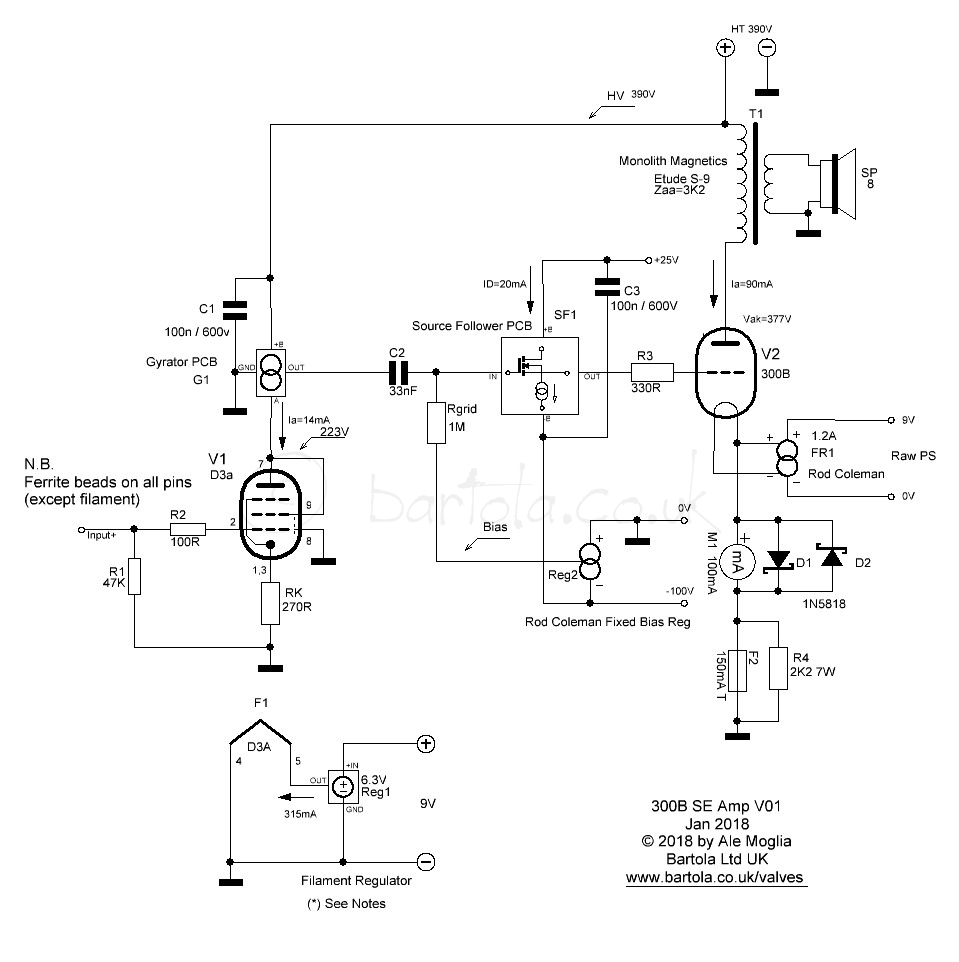
The D3a in triode mode is probably one of the few valves which can do 250Vpp without any issues and very low distortion. Below is a THD plot for 240Vpp which is impressive. You won’t get this level of performance if it’s not with a hybrid mu-follower. Here is the amplifier circuit:


If you are interested in less gain and adding a pre-amplifier stage (e.g. like an 01a) then you can look at implementing the 6e6p-DR (or a 6e5p) like in my original design:

I really like the sound of this valve and has a lower H3 component when driving large volts. See below:

Here is a plot of the frequency response of the driver. Less gain of course (i.e. 30dB) but with great performance:

Alternatively, if you need more gain, one of my favourite drivers is the 6SF5GT. This one can give you 40dB in sterling performance with a hybrid mu-follower (a.k.a. gyrator) topology. You need to bias the valve a bit higher than the D3a and similar triode-strapped pentodes. Therefore the HT has to be increased to 450V. You can add a drop RC to feed into the 300B output stage (R3 and C2 below):

Here is the frequency response of the driver stage:

There are so many options to work on. Even the lovely Russian 6C45P triode (which is a wild oscillation beast) can be used at a gain of 32dB:
 Amazing response as well. You need to set the anode voltage to 200V and the cathode resistor (un-bypassed) to 120Ω.
For me this time round, I will build the 300B output stage separately so I can play with different drivers. Yes, I want to experiment as usual.
I have EML45’s, center-tapped in a slightly modified Bottlehead Steremour. I don’t know much at all about your level of genius, but I can say the amp sounds gorgeous, when it works. I fear my soldering skills have caused some issues, sadly.
Ale,
in triode mode D3a try G3 at A once, please
Hi Rajko, good point. When I looked at the valve socket I had all the grids tied up to anode. I don’t know why I draw it like that. I think I copied and pasted diagram from 6e6p-dr design.
What is your experience in terms of sound difference? Can you perceive any change apart from total anode current increase?
Hi Ale,
I always use G3 tie to anode via 100R. IMHO the sound is better than tied to cathode.
I’ve been using similar amplifier (CCS loaded D3a, powerdrive, EH 300B, 5k:8) for ten years, with only a small difference: up to 10W in A2 mode (EML300B’s grid is too fragile for A2 mode!).
Try to use old type green LED without D3a cathode resistor (better tone).
Hi Bela, contact me about my SE. Can’t use diyaudio.com for some reason.
Cheers
revintage/Lars
Not only increase the anode current but also decrease the total Cgk.
On my 300B and 6C33C SETs, all triode mode pentode drivers sounds more comfortable and relaxed. I tried D3a, C3g, 18040 (old Philips predecessor of Germany C3g).
My friend reported that it was also on his grid-choke 300B SET as well as on the D3a-E180F RIAA preamp.
All grids I connect to the anode via Kiwame or some other low value CC resistors.
Best DIYing Ale. It’s always very interesting to look at your DIY.
Excellent feedback and input Rajko and Bela, as always!
I will update the diagram to reflect the G3 wiring to anode.
Regarding the D3a cathode resistor, yes you’re right. I have used it with a SiC diode which I found sounds better (in my opinion better than the LED) but not in a driver position. Will try it again. Good suggestion.
I wasn’t planning to use the 300B in A2. The EML300B is too expensive to adventure on positive grid current. I don’t need that level of power anyway 😉
Cheers
Ale
Ale,
why do need SF? I thought SF is only needed when you have low current driver? I see D3A already has enough current to drive 300B
regards
Ferry
Hi Ferry
You’re correct. Main purpose of the SF here is to accommodate the grid negative bias needed and provide DC coupling to avoid blocking distortion due to the coupling cap when there is grid current (e.g. approaching to 0V or when driving a bit into A2).
The coupling cap is moved to the input of the Source Follower. In this way you can reduce the size of this cap as you can add a higher gate bias resistor (e.g. 470K or more) without affecting bias (like with a grid leak resistor). Also you can then use drivers without the current drive capability of a D3a or similar (e.g. a 6SF5).
Cheers
Ale