Since my early days of valves and DIY audio, I developed an obsession around testing and tracing valves. This led me to design and build my analogue curve tracer which I used for many years successfully until I build my uTracer, which was a great innovation in curve tracing. I do have many valve testers (some which I made myself) so why building another one?
Well, Chris Chang from Essues Technologies developed a fantastic new digital curve tracer for valves, the eTracer. There are a few things which will grab anyone’s attention on this curve tracer. Firstly, the power supplies can accommodate a large range of valves which the uTracer can’t. HT can go as high as 750V @ 300mA and the grid supply down to -170V! This is exactly what you need to test your transmitting valves or even a 300B. Secondly, the tracing speed is surprisingly fast. This is a nice feature, specially when you want to trace pentodes at various screen voltages to develop a Spice model for example.
I have a pair of Sylvania’s SX-201a which sound superb. My preferred ones for 01apreamps. I’m looking at revamping my 01a line-stage shortly. Here is a trace of the anode curves for one of them:
The uTracer is a fantastic tool clearly. Well done Ronald!
After playing for some time with the uTracer, I found that the tracer wasn’t measuring accurately A2 curves. Ronald clearly advised me (as explained on his site) that uTracer wasn’t designed for this purpose although there was a great trick to use the screen driver to generate the A2 curves and also measure grid current. Measuring grid current is key in A2 mode so a better grid current model can be derived to better simulate the non-linear and low impedance behavior of the grid in positive bias.
My incarnation of the uTracer is not neat. I’m using my existing analogue curve tracer. As shown in the pictures below, my current tracer have a plethora of sockets and just adding right jumper cables for anode, cathode, screen and grid connectors will still give me the flexibility I had with my analogue tracer
Additional 3,300uF capacitor across C13 to help A2 traces
My version of the uTracer
uTracer using my analogue tracer sockets 🙂
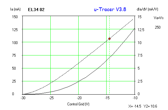
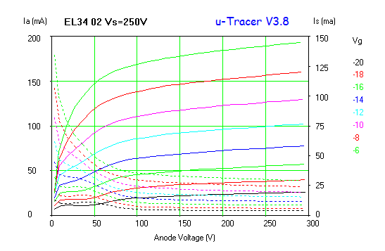
The process of generating the A2 curves (and SPICE model) starts by plotting the normal curves. The uTracer is great for this. Then you have to overlay the A2 curves in Excel (or whatever tool you prefer) to combine both set of curves.
Didn’t take as long as I thought to build the new anode current sensor for the valve curve tracer. A simple PCB was used to solder directly the components for a quick solution. Here is how it looks:
I tested this new circuit with some valves from high transconductance to low current ones. The current amplifier works like a charm. I used a CCS first to calibrate the x10 output and found a great linearity from 1mA up to 100mA. Currently I used my bench power supply to test this but I’m planning to do some major surgery to the tracer and include this sensor inside the main chassis.
With a dual 15V supply the AD8479 can work with up to 600V in common mode. This is perfect for my tracer and can be used to sense anode and screen currents.
After some feedback from the DIYaudio forum clearly the INA122 was a killer in this application as no differential signal was used at the output stage. Despite having an INA122 around, I looked at an alternative option with a good op amp I had at hand. The LM833 is a dual low noise op-amp that can do the trick here:
After nearly 18 months of using the curve tracer, I guess that everyone would find ways of improving any testing equipment. I personally traced so many valves on this curve tracer that I already know all its limitations, advantages, what it likes, what it doesn’t like, and all. Just like a pet (or a partner) or whatever analogy you would like to make.
Tracing anode current has always been a real challenge. I opted for sensing the cathode current as it’s easier to implement. For low current valves (or high gm ones) I have a set of cathode resistors to avoid any significant impact on the bias point.
Obviously sensing anode is the right way to go, but that is a hard challenge if you are looking at just using sand. A transformer couple version is fine, but not as easy as the op amp in the cathode.
Generally you would like to sense screen current and also grid current if you are looking to create some SPICE models for the valves you are planning to use.
Grid current in A2 mode plots are scarce. They are only available for transmitting valves. If you want to use 2A3, 300B or 45 in A2 you won’t find those traces around. Hence, your SPICE model will lack of accurate response in A2, unless you are able to plot the A2 grid current of course.
Here is the new circuit based on the AD8479 which will allow 600V in common mode. This op amp will help us to easily sense not just anode, but also screen and even grid current if necessary.
The AD8470 stage will convert the current across the sense resistor. The gain stage is provided by the INA122. A set of preset can be arranged to provide x10 or x100 or whatever gain you want to implement that will fit your oscilloscope Y input.
I will need to breadboard this and report some results…
Ale
After being out of action for over a month due to visits, holidays and business travel, I finally got the opportunity to get my hands back on the 600V bench supply. I need to repair my valve tracer, but firstly need the bench supply back again. Otherwise won’t be able to do all tests I want to around my 814 DC-coupled SE amplifier and many driver stages I want to try on my workbench before moving to the next stage.
An improved design to avoid fireworks
Tired of my old HT (+600V) variable bench power supply to suffer collateral damage when accidentally shorted whilst testing transmitting valves for output stage (i.e. FQP3n80c MOSFET passive regulator blowing out), I decided firstly to decide a simple and yet effective valve stabiliser. As nothing comes for free, these were my design constrain factors:
Input raw supply is +620V @ 100mA
Filament secondary winding is 15V @1.5A
No additional secondary winding is available for a floating screen supply (e.g. pass valve is pentode)
Output voltage ideally should be 0-600V
So with the restriction of not using a pentode as pass valve, I looked out for candidates to match my requirements and instantly thought about GU-50 in triode-strapped mode. Yes, I know that UG2 limit is 250V, not 1,000V as anode max voltage. But, in triode strapped specs are not shown. As recently checked this with the 814 triode strapped, and seems to be ok UG2=Ua in triode mode. 7N7 also said this was ok and Morgan Jones previously tested this as well with similar valves.
So, question here initially was: could the GU-50 withstand 600V in triode mode or should I needed to look out for other options?
After asking for some help in DIYaudio forum to see what was the best option on this topology and the recommendation was to use the GU-50 in “right-handed mode”:
GU50 right-handed
In this mode GU-50 was able to provide the regulation required (or close to it) with minimum driving requirements (i.e. 0V to +15V)
First version of the passive regulator:
The MOSFET is in source follower mode to provide the necessary grid current, albeit not sure how much grid current the GU-50 needed in right-handed mode. So the value of R6 must be adjusted on test. In order to survive an output short, R6 needs to be in the order of 100K and 3 or 4W to avoid blowing up the 18V zener protecting the grid.
The circuit above is very interesting as the anode dissipation of the GU-50 is very handy for this setup and requirements. Is important to highlight that the circuit has no regulation, so if this is a requirement a different topology must be explored.
If we look at the sandy option here, then the following equivalent is comparable:
R2 and R3 are required to protect silicon from output short. Q1 provides current limitation with R6. This topology suffers from same issues related to regulation as previous circuit.
A big issue on the two circuits presented before is that the potentiometer is stressed at full raw HT supply. This is far from ideal and despite the specific power requirements of the pot, we also need to ensure that the part can withstand the voltages used.
A slight modification (requiring an additional LT supply) can solve this problem:
Now P1 is connected to 15V. The gain of the M2 stage is significant so stability of circuit above is an issue now.
So if we have already introduced an LT supply in the circuit, then is a better choice to look at a feedback regulator.
A more complex circuit indeed, but a more effective one. The op-amp provides regulation by sensing output from R7 and R8 divider and comparing it to the stable reference from the output of P1. R10, R9 and C1 limit the HF gain response of the op-amp. R12/C3 and the 10pF FKP2 Wilma cap across R7 optimise the HF response of the overall regulator. D1 will protect the op-amp input (specially if 10pF cap is fitted). R1 is an additional protection for M1. M1 requires a good sink if wider regulation is needed. When output voltage is low and high current is drawn, then M1 is bearing all the effort and will dissipate a lot of heat (just do the maths).
The raw supply stays the same, however the gyrator stage was optimised as shown below:
The MOSFET was changed for am 1000V TO220FP plastic package one which is better from an insulation perspective given voltages used in this circuit. R5 and R6 changed to 150K 3W ones to provide protection to the zener and M1 in case output is shorted.
This is a great unknown russian DHT. Just like his brother 4P1L :). An output beam tetrode with direct heated cathode filament. This 18W valve is a great candidate for an output stage, with its standard filament voltage of 6.3V and octal socket, many ones out there will be really attracted by this valve as it can easily be adapted in many classic output stages.
I did some initial tests about a year ago and this valve proved to be very linear and capable DHT. Was planning to use it as a pre-amp valve with filament starvation as THD results were more than promising.
Paul Leclerq, Andy Evans and I now want to test this one as an output valve. With 18W+3.5W=21.5W of anode power capability, it’s a great DHT for output stages clearly.
So I went back to the workshop to trace the curves first.
Finally, here is a THD plot for the 6P21S showing how linear this valve can be. The following quiescent point was found to be very good for this valve: