I’ve been posting about the use of source followers in the circuits with some interesting results from testing. Some interesting posts to read, If you haven’t read them so far:
- Slew Rate, Slew Rate (Part 2), Slew Rate (Part 3) and Slew Rate (Part 4).
- 6SF5 driver for 300B/GM70/813 SE Amps
- DHT Phono Stage Test.
After several tests over a variety of circuits, I finalised the prototype for a Source Follower PCB. The circuit is incredibly useful. Some examples of uses cases are:
- Amplifier output stage grid drive
- Screen drive amplifiers
- Screen voltage stabiliser for pentode stages
- HT voltage stabiliser for preamps
- Buffer stage for high-mu/high-anode resistance stages – either triodes or pentodes (e.g. Phono)
Some key aspects of the board are:
- The PCB has been designed to accommodate all sorts of power MOSFETs (both TO-220 and TO-247), in particular the high transconductance and low Crss ones which perform the best in this role.
- The tail CCS is simple and leverage the option of using same MOSFETs.
- The board takes into account the use of any bipolar supply up to 450V diferential. You only need to change a resistor depending on the supply voltage levels and make sure there is a sufficiently big heatsink on the MOSFETs.
- There is a current limiter circuit built in to protect screen or grid from excessive current. This is also very useful when the board is used as a voltage stabiliser for a preamp. You can limit the peak current and avoid destroying the MOSFETs when capacitors are charged or if accidentally the output is shorted. This circuit can be bypassed easily with a jumper.
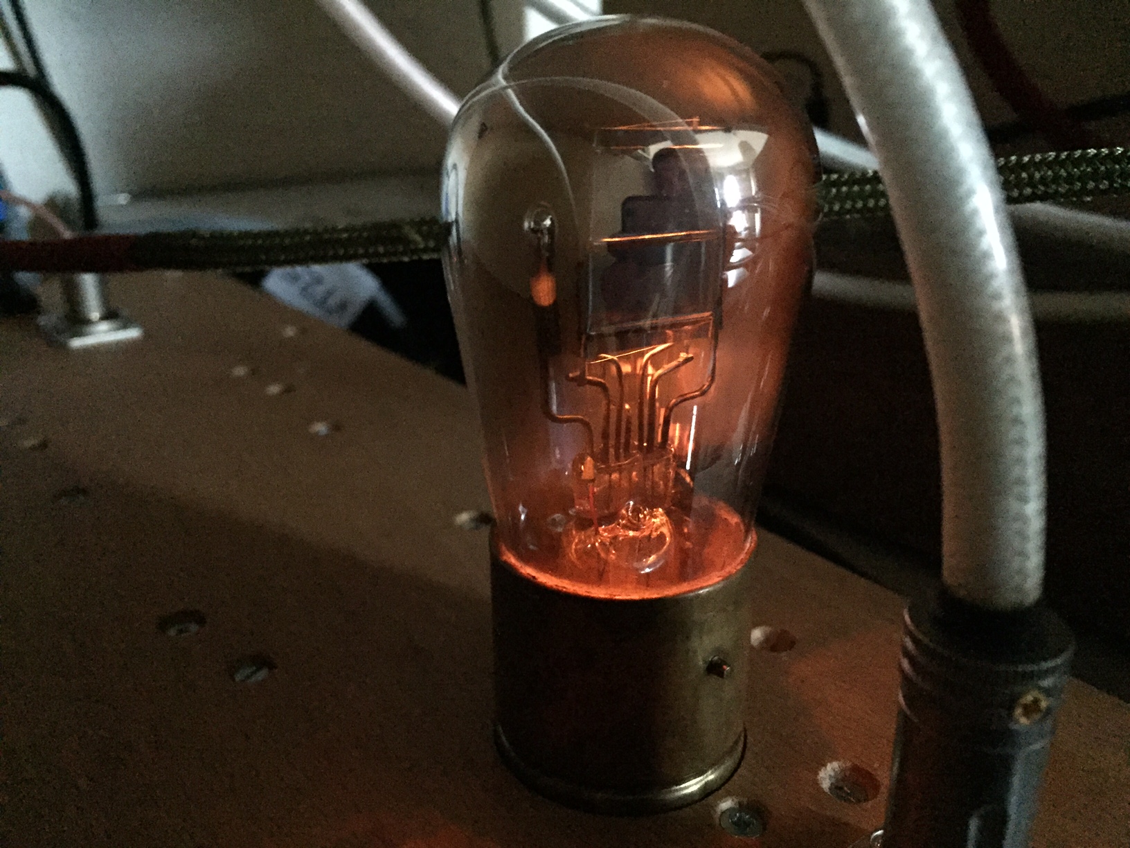
Here is one of the boards submitted to the usual abuse during testing:

This is a very useful PCB in my view which can be used extensively in preamps, line stages and amplifiers.
If there is sufficient interest, I will run a batch of PCBs for the DIY audio community:


