Short of sand

Firstly, my apologies. It’s been long overdue to get back on this blog. I receive several emails from people asking me to share more. I hope I will, when I get the time and energy to get back on hi-fi audio projects. I still work a lot on synthesisers which keeps me very busy when I catch a glimpse of free time from my hectic day life.

We’ve all been hit by the short of semiconductors. Yet, the HV precious parts are in shortage as well. Luckily some of the key parts like LDN150 and IXTP08N100D2 are back in stock, not sure for how long. These are key parts for building any CCS or hybrid mu-followers for audio circuits.

Continue reading “Short of sand”

Gyrator PCB Hack: final Enhancement Mosfet design

I evolved my previous design here, thanks to the help of Rod Coleman and fruitful discussions with him.

There is an option to improve the design by bootstrapping the top MOSFET to avoid using a bias Zener and allow the bottom device to have a constant VDS. This can be achieved by double bootstrapping the FETs. Here it goes:

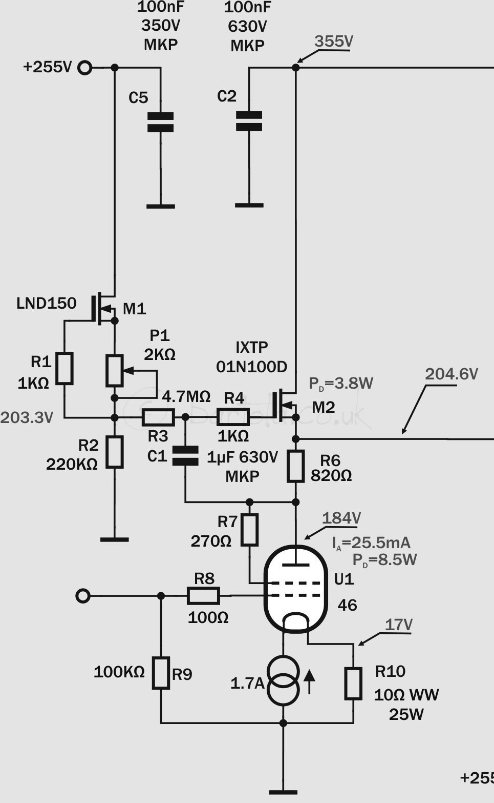
Similar design as before. Only difference is that R7 is used to create the bias of T3, and thanks to the bootstrap of C2, the bottom FET (T4) now operates freely regardless the swing. D1 is needed to protect T4. R7need to be adjusted considering the output voltage expected as well as the maximum VDS before D1 starts to conduct.

There is an stability challenge and it can be addressed as Rod Coleman clearly points it out, a “guard ring” :

The other pro trick is the guard ring: this will dramatically reduce problems of dc-drift, if the PCB surface gets contaminated, e.g. when soldered with some old or poor-quality solder. Or damp air, fumes etc. It’s a conductor (pcb trace) around the high-impedance network formed by the 10M resistors. A staggered-pinout version of the TO220 is needed to implement it, as the TO220 is the hotspot for leakage (B+ of drain to the 10MΩ-driven gate!).

If there is a leakage path, it leads only to the guard ring, which is only a few volts away from the intended bias – rather than if the leakage can reach ground or B+, which would drive the circuit crazy. Connect the guard to a low-Z source – the Output in this case.
 
Anyway – I hope it is useful in some way!
(Rod Coleman)
 
How well it performs? Here you can see – no guard ring here, just adapted standard PCB for testing purposes:
Not bad at all with 3MHz bandwidth. However, considering the circuit complexity, I much rather stick to the depletion version which performs much better in my view:
 
Nearly 5.7MHz under same conditions!
 
Cheers, Ale
 

Upgrading the DHT filament regulators

I upgraded the DHT filament regulators to version 4. Rod has released a new kit which introduces temperature compensation for high current filaments. This is a key feature in my 4-65a design and I shall explain why:

Continue reading “Upgrading the DHT filament regulators”

4-65a SE Amp: 46 Driver Gyrator

 A day of PCB etching

20121230-194358.jpgAfter a lot of work today in designing many PCBs, I finally got a pair of mu-follower MOSFET gyrators for the 46 driver stage.  The driver has to provide very low impedance to operate the 4-65a output valve in class A2. The gyrator in mu-follower configuration will enable the right bias point as the amplifier is DC coupled as well as maximum signal (and current in A2) with minimum distortion.

Many don’t like sand at all in their amplifiers. I have a lot of experience with gyrators and CCS loads in pre-amps and drivers as well. I have to say that with MOSFETs gyrators the sound is really nice. For an A2 driver, not many options are available and the gyrator is a great choice for this job.

I built two PCBs (one per channel) and the circuit is the classic depletion-mode MOSFET gyrator based on the high-voltage IXTP01N100D. I guess that a DN2540 should work as well here but I’ve been saving the IXYS for this occasion. The reference voltage for the anode bias point is provided by the CCS formed by M1 (LND150) which provides a higher impedance in AC improving the frequency response of the gyrator.

4-64-65a driverThe 46 is operating in triode-mode and filament bias with a Rod Coleman filament regulator. R6 is approximately 1/gm and output voltage is set by P1 to achieve the 4-65a bias point as the amplifier has stacked power supplies given coupling is DC, so no capacitors in the path to the grid.

Next: some tests on these gyrators and the filament boards…


45 SE Amplifier upgrade

Replacing driver for 7193 valve

Well, after nearly 12 months of playing relentlessly my 45 SE amplifier, had an unexpected failure in the power supply (passive regulator) which forced me to do maintenance to the amplifier. It was a great opportunity to remove the 6J5 driver and do a quick swap for the greatly respected 7193 (i.e. military version of the 2c22)

45SE Amplifier upgraded with the 7193 drivers

Bias point remains unchanged: 7mA and 260V for maximum swing and minimum distortion. Need to look at my notes, but I remember that I was something around 0.30% at 100Vpp driving the 45 (which is not an easy load for anyone).  Driver configuration was not changed, so had the 7193 now loaded with same DN2540 single transistor gyrator and mu-follower output for lower impedance. The valve was biased at about 8V with an LED array.

7193 in action

As a test, played the fantastic Symphony No. 3 from Henryk Gorecki….