UV-201a final version – finished!

After doing all the soldering part (which I enjoy much), the preamp is now finished. It sounds as good as the original breadboard:

For the curious ones, here you have a picture of the inside:

The teflon sockets are bolted straight into the 4mm top aluminium plate. No microphonic noise this way. Rod Coleman V7 regulators set to 200mA. A pair of Russian Military NOS wire-wound resistors in parallel provides the filament bias. The gyrator PCB is set as per original circuit and each valve at 3mA. These are DC coupled to the MOSFET follower PCB set at 10mA each. The output is then taken out from a pair of FT-3 teflon caps. 

Now to enjoy this beauty!

4P1L / 4П1Л Siberian Gen4 in Screen mode

Some time ago, I did some initial experiments with the 4P1L (4П1Л) with the screen performing as anode instead. Some DIYers claim the improved sound of the mesh type anodes. Kees Brakenhoff kindly sent me some PL519 to test in screen mode. He has done multiple builds with this mode of operation with great results. Unfortunately I’ve not had the chance yet to build such an amp.

What I could do instead though, was to mod very quickly my 4П1Л preamp to screen mode. It was a very easy and fast modification. I kept the same heating wiring and just adjusted the screen (anode) current down to 10mA: Continue reading “4P1L / 4П1Л Siberian Gen4 in Screen mode”

UV-201a DHT Preamp Revisited


I previously implemented a preamp with the UV-201a. These are very old globe valves, somehow fragile and hard to get in good shape. Despite all this, it’s a superb valve. I have managed to acquire a decent set of them to pair the best valves to use in my preamp.

Recently I developed a prototype PCB for the source follower circuit. The source follower is ideal to place at the output of this preamp due to its low driving current. My 4P1L PSE amplifier will be pleased with more current to pump the Miller capacitance effectively. 

Continue reading “UV-201a DHT Preamp Revisited”

Gyrator PCB Update – Rev07

The gyrator PCB has been updated to fit now a wider variety of lower enhancement MOSFETs with low capacitance and high transconductance. The best examples are the BSH111BK and BSN20BK which are great options for currents above 25mA:


The board offers now all the flexibility needed in terms of different TO-92 and SOT-23 package pin-outs to use whatever FET you want.


4P1L (4П1Л) Siberian Gen4 – DHT Preamplifier

The return of the Siberian

After trying out so many DHTs and pre-amplifiers, I decided to wire up my 4P1L preamplifier Gen3 and fit the gyrator board to drive my 4P1L PSE Amplifier.  

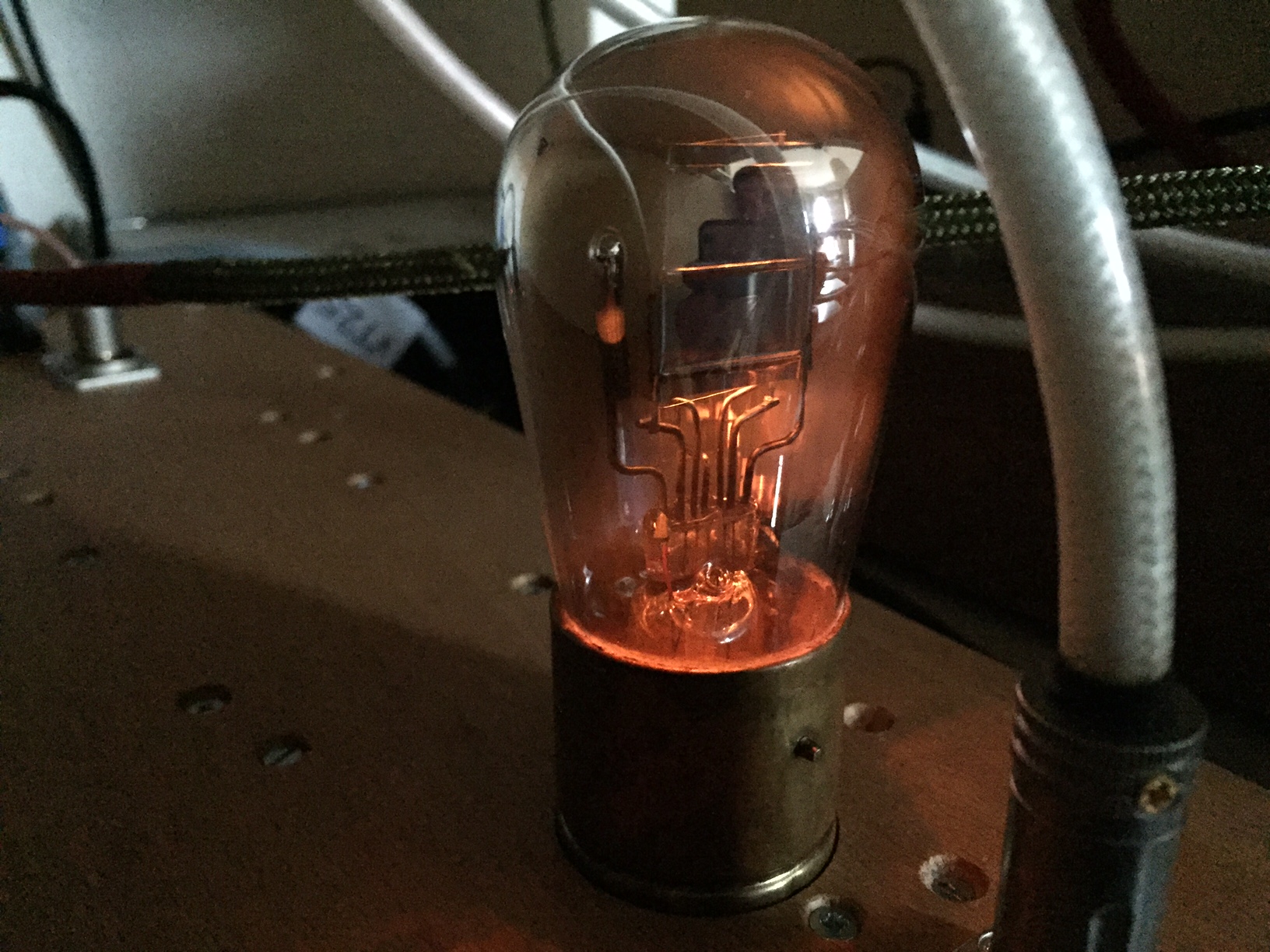
I have a pair of 4P1L/4П1Л dated 1968 which are properly burnt in. I’ve used them lately in my previous preamp incarnation with great results. 

The circuit doesn’t need explanation, I think I’ve covered this repeatedly for a long time.  I will only point out the differences:

The main change was fitting a pair of Russian wirewound 27Ω resistors in parallel to get closer to the 15Ω used in this position. I found these Russian wirewound resistors to sound extremely well as filament bias resistors. I tend to be skeptical about the “sound” of some components in circuits, however, they do make a big impact in the cathode of a filament bias arrangement. 

The gyrator has my preferred combination: IXTP08N100D and BSH111BK. I have now an upgraded PCB Rev07 which fits the BSH111BK and similar FET and I will offer them shortly. 

The latter benefits from the 30mA idle current. The result is lower output impedance whilst providing a great frequency response overall.

M3 needs a proper heatsink, it does get hot with about 2W of dissipation. 

How does it perform?

Well, this valve has the reputation of amazing performance and low distortion. The gyrator setup provides the best out of this valve in my view. You can get a flat response as well as great bandwidht from 10Hz up to 3MHz loaded with 100kΩ:

The distortion is very low and is lower than 0.05% below 10Vrms. Dominant H2 with a lovely harmonic profile characteristic of this valve. 

How does it sounds?

i’ve been listening and using this valve extensively since 2011. I have to say that it sounds amazing. I never get tired of its sounds. Before I listened to a 4P1L-4P1L system and found a slight edge on the sound (probably due to its H3 component) which I don’t hear on my system. The drive, clarity and tone is amazing. It can drive the 4P1L PSE perfectly well and you get a strong and clear bass. Very powerful. My +600 hours 4P1L are very quiet in this setup, no microphonic noise. I don’t have even dampers in the 4P1L sockets!

Anyway, if you need 19dB (x9) gain in your system or you need a driver for your  SE amp, then this is the valve to go. I Still can be found cheaply and is a great contender to the thoriated tungsten filament DHTs like 01a and VT-25. 

Build this one and enjoy!

Gyrator FET options (More!)

Someone had to invest and sacrifice some gyrator boards to test various lower FETs (either depletion or enhancement devices as well as TO-92 or SMD options). That was me. 

Why? Because I want to push this circuit further and find the best options as well as provide to the builders out there some other device alternatives when they can’t solder SMD components. 

So let me present you the abused test mule and the various boards under the mercy of my tests:

Boards with different FETs under test

Continue reading “Gyrator FET options (More!)”

Gyrator PCB board updated (Rev06)

After some further testing and prototyping, I’ve updated the gyrator board PCB to provide additional protection to the lower FET device with:

  1. Protection Zener (D3) between drain and source (through-hole)
  2. Back to back protection Zeners (D1 and D2) between gate and source to ensure positive gate bias for higher currents on jFETs and use of enhancement MOSFET

Layout was carefully adapted to ensure track separation due to HV in place. Result is that the new gyrator board provides all protection needed on the lower device and simplifies the build process


Here is an example of a completed board tested:

Gyrator Board Rev06


Building gyrator boards

I’ve been on some business travel so haven’t had much time to work on stuff, however I did get a set of gyrator boards for a friend and a customer:

  1. BF862 configured for 4P1L preamp
  2. 2SK170 configured for 01a preamp

4P1L preamp with BF862 gyrator

Many have asked me about this preamp with gyrator load. Here is the latest implementation which I preferred most in terms of sound. The mu resistor is 470Ω which is a nice compromise between BF862 transconductance and distortion. I adjusted it on test. I use a 100nF for C1 so R6 is 10MΩ. R4 can be either 300KΩ, 330KΩ or even 390KΩ. Difference would be only on the voltage range for the CCS. I found running it at 25mA to be perfectly fine, some BF862 can even do J310. I prefer this SMD compared to the J310. It performs much better even at high frequency:

4p1l-preamp-gen1b-gyrator-pcb-detailed


4P1L gyrator boards
4P1L gyrator boards
Continue reading “Building gyrator boards”

Gyrator Test Mule: 4P1L Preamp

4P1L gyrator test mule

It’s always great to come back and revisit a great design. The 4P1L preamp performs flawlessly so I tweaked the gyrator board to see how it worked with the BF862 FET. The result is great, it sounds as good as it measures:

4P1L Test gyrator board

The 4P1L is biased to 150V/25mA which is the maximum current that the BF862 can do (IDSS max). You can see that the frequency response is flat up to 1.5MHz. The LF response of my test mule is affected by the AC coupling of the measuring gear. However it should be around 5-10Hz.

The distortion of low-level signals is really good:

THD @ 4Vrms
THD @ 4Vrms

Predominantly H2, it’s very nice to see THD<0.015% for a 4Vrms output. The load is 100KΩ which is the typical input impedance of an amplifier (with exception of solid state gear)

This low distortion manifests across the entire audio band (ignore the THD below 20Hz which is a byproduct of my testing gear):

THD version frequency @ 4Vrms

The nice thing to see also, it’s how well the 4P1L can drive larger voltage swings:

4P1L THD @ 10Vrms
4P1L THD @ 10Vrms

We can see H4 popping up, however odd harmonics are lower (H5 in fact is higher than H3). THD at 10Vrms is still below 0.03%!