Last week I did some preliminar tests with the LL2746 in 1:2 step-up mode. Despite having measured good results with it, it will be a challenge to drive grid current given that the output impedance of the 4P1L will be multiplied by 4 so about 5KΩ.
Before looking at the LL1671/20mA which is suitable for multiple driver valves, let’s see how the LL2746 driver performs with the addition of the input step-up microphone transformer LL7903. I’m currently using the LL7903 in my 814 SE A2 amplifier and sounds really nice. The LL7903 was wired up in 1:4 setup so gain can get about 63:
After a recent discussion in the DYI Audio forum about the 4P1L drivers, I decided to do some quick tests on an idea I had around to use a step up transformer (1:4) – 4P1L and step up interstage transformer (1:2) to drive a 300B or similar using the 4P1L in filament bias.
First suspicion is on whether the 4P1L has the grunt to drive a capacitive load which would be a real challenge in a 1:2 step up as load capacitance is multiplied by 4 when impedance is reduced by a factor of N^2=4.
I built a test rig with the 4P1L in filament bias using a 15Ω wire-wound filament resistor and connected the filaments in parallel to obtain easily a nice bias voltage with 650mA of filament current. Also lower Rf will improve the low frequency response as helps keeping low the output impedance:
4P1L rat nest
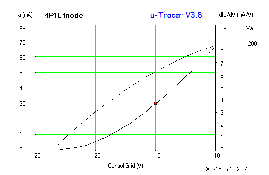
The valve was biased at Ia=30mA / Va=160V and grid bias is about -10.2V. A 10KΩ resistor was added as a primary Zobel as per recommendation of the datasheet. Then it was replaced by a 25kΩ potentiometer (P1) and the right value was found by looking at the frequency response.
Initial tests showed a very good response at 1kHz with only 0.24% THD @200Vpp output. The gain is approximately 16. The mu of the 4P1L with paralleled filaments is around 8 and lower than when used in series which is approximately 9-10. Albeit the results were promising initially, the real test of this stage is by looking at high frequency response where the capacitance will makes it real pain.
We’re constantly obsessed to get the most out of our lives. Not a product of the capitalist world we live in, but a fact of our human nature. Its evolution.
When it comes to sonic power, unfortunately we are not too distance from this thought. We want more Watts. Yes, pure power. My generation back in the 80s got misled by the audio product marketing and their unrealistic metrics (e.g. PMPO) to fudge the real power of a solid state amplifier.
Continuing with this series of blog posts around the 6C4C push-pull design. As suggested my 45 in my previous blog entry, here is the 4P1L-4P1L version:
The first 4P1L driver stage remains unchanged, as does the output stage. The addition of the 4P1L differential pair with CCS tail and LL1660/pp IT is the main change of this design. The LL1660 is configured in ALT M or 2.25+2.25:2+2. I guess that a different IT could be used instead to get a lower output impedance on the diff pair and improve the performance in A2. The amp has more gain that I need in this configuration as it delivers its maximum power (circa 8W) when input is 1.2V peak.
So how does it performs?
Very low distortion indeed. About 0.06% up to 8W. Mainly odd harmonics dominating the sound of this amp.
I love the sweetness of my 45 SE amplifier, but you know what? A great push-pull (PP) amp has a fantastic presence, bass and dynamic response. Whenever I listen to a good PP amp, I get to the conclusion that I need to have different amps ready to be played depending to the music I want to listen to! My last two years have been devoted to what Morgan Jones calls in his book “single-ended madness”. And yes, my 4-65a SE in class A2 is slowly coming to life and when ready so then I will be properly mad.
6C4C amps I listened so far made a great impression both in SE and in PP. Owning all components required, I embarked on refining a full DHT push-pull design and again, cap-less (excluding the power supplies of course).
Last week I looked at optimising the 45 loadline in A2. Clearly we shouldn’t be attempting to get more than 2W from this valve without a significant level of distortion. However, having about of 3W would be attractive for the transient response of this amp.
So how will this circuit perform in a simulation? Let’s see what the spice results are:
The THD is significantly better due to the harmonic cancellation between the two stages. The driver distortion is 0.3% at full tilt (150vpp) and this could be improved. I guess the 6e5p could do better, but interesting to see how the cancellation of harmonics may play around. The new operating point and the stacked supplies will demand different MOSFET parts of 1kV for sure…
After the initial tests done with the 4P1L in pentode mode and filament bias, I thought a bit about how this driver could be implemented in practice. I may try this configuration in my 4-65a SE amp, but am not urged by this at all.
The screen supply is formed by a gas valve (SG3S) which provides a very stable reference when feed by a CCS. In this case the cascoded pair M3 and M4 will provide in conjunction with R4 and U2 a very low noise screen current to U1. R9 has to be adjusted on test to set a current of about 15mA on the CCS. The 4P1L will draw 1.8mA at 81V as screen current, so R4 may also need adjustment to set the right operating point.
The driver should provide about a gain of 150. Driving easily a transmiting vale (or why not a 300B 🙂 ) in class A2 with this configuration. My tests showed a maximum THD of about 0.27% at 200Vpp.
Gain could be reduced if needed by tweaking the RL. And if stacked supplies are not used, then a single +400V supply could be used with additional dissipation across the reference currents (M1 and M3/M4).
After the early experiments with the 4P1L driver in pentode mode, I decided to look at improving it somehow given advice given. The gyrator load is not a good match for a pentode unless the reflected impedance is low enough to control the gain of the stage. Gary Pimm recommends:
“In the driver experiments the plate resistor was increased to a value larger than in traditional Pentode driver stages to get more gain.A CCS was placed in parallel with the plate resistor to add plate current to compensate for the high value plate resistor. This allows you to have independent controls of the gain and operating current. The resistor is chosen to set the gain and the CCS is used to set the Pentode operating current. To maximize the circuit performance the resistance in the screen circuit is adjusted for minimum distortion. There are draw backs to this- The circuit has to be tweaked for each tube. As adjusting the screen voltage and resistance also effects the gain of the stage you have to compromise some to have the gain match between 2 channels. This is not a circuit where you can swap tubes around without “calibrating” the stage on the test bench.Another interesting way of applying the circuit is to place the plate resistor in parallel with the Pentode and have the CCS supply all the current needed by the stage. This allows the Pentode driver stage to have PSRR similar to CCS loaded triode stages. It also makes the signal current loop very small including only the Pentode, cathode, and plate resistors. The noise and capacitor colorations of the power supply are quite effectively removed.”
So I opted for adding a resistor in parallel (RL) to adjust gain, minimise distortion and improve PSRR:
The load resistor is 68K. I optimised the operating point to reduce distortion at maximum swing (i.e. 200V peak to peak). The input impedance of the soundcard interface which is 100K didn’t produce a significant impact on the distortion when measuring from the anode output or in the mu output:
Interesting to see that distortion is now nearly half of previous operating point and 0.27% for 200Vpp is very good.
The screen current is approximately 1.8mA at 81V bias.
4P1L is a sublime DHT. As shown before it’s one of the most linear valves in triode mode. I built a breadboard in filament bias to test 4P1L as a driver using a MOSFET gyrator in mu-follower mode:
My test set can only drive the 4P1L output to 30Vrms and the distortion is only 0.027%!
I was intrigued by the performance of this driver in pentode so did a quick modification to provide a screen fixed voltage instead via a source follower and adjusted the bias voltage to minimise distortion. I found that a bias of about 120V was the best. This setup wasn’t the ideal one as in filament bias the frequency response is really poor as there is no cathode resistor bypass. The gain is about 200 with the gyrator used:
A distortion of 0.58% @ 200V peak-to-peak is really good. The filament bias is forcing the pentode to operate with low anode current so I guess that with a lower bias point performance will improve. I will have to test this.
The measured THD was:
0.125% @ Vo=100Vpp
0.34% @ Vo=150Vpp
0.58% @ Vo=200Vpp
Interesting to see the increase of H3 and H5 as a result of the pentode operation.
The breadboard for pentode can be improved for sure. I will look next at reducing the bias voltage as a first step. Interesting results which show that 4P1L is a great driver both in triode and in pentode modes.