Gyrator FET options (More!)

Someone had to invest and sacrifice some gyrator boards to test various lower FETs (either depletion or enhancement devices as well as TO-92 or SMD options). That was me. 

Why? Because I want to push this circuit further and find the best options as well as provide to the builders out there some other device alternatives when they can’t solder SMD components. 

So let me present you the abused test mule and the various boards under the mercy of my tests:

Boards with different FETs under test

Continue reading “Gyrator FET options (More!)”

Russian PSE in Steroids (01a into 4P1L) – Part IV

AM-cartoon-serie2_0004More power

Our previous west meets east circuit can be improve further. In fact, a compromise made with the filament bias design is that coupling between driver (FET follower) and the output stage wasn’t DC. We want DC coupling to get best performance, to ensure we can drive well the output stage and provide sufficient grid current even when not operating in A2.  This can be done with filament bias, however, since we are already introducing a negative supply, I’d prefer removing the filament bias and go for proper grid bias to get best performance of output stage in terms of  maximum power and linearity.

The below circuit can be easily implemented with just few modifications from previous version:

01a-4P1L-PSE-v05

What has changed here? Not much, the coupling cap C2 is now between the gyrator and the FET follower. The gate bias resistor R6 provides high impedance to the gyrator load to ensure maximum performance of the 01a driver (minimum distortion given size of load). Not as good as previous version, but good enough. The R6 is connected to a potentiometer which sets the bias voltage. The bias voltage is derived from V2, the -50V negative supply. You can see that this circuit will put more stress into the M1 FET as now there is an additional 25V of drop across it so power burned on this device increases.

The output of the follower is directly coupled (DC) to the output stage. The filament bias resistors are removed and we use the Coleman regulators directly on the filaments of the 4P1L.

This amplifier responds better to the grid current of the output stage once the output power goes over 3.5W. At 4.5W the distortion is just above 3% (3.2%) with a 3Vpp input signal. A tad more and you can get to the 5W and a bit more into A2 operation.

Russian PSE in Steroids (01a into 4P1L) – Part III

From Russia with Love

Copyright by Justmeans
East-West Divide, Copyright by Justmeans

The interesting combination to explore from our previous designs is to mix some western valves like 01a into the Russian parade.

The result would be quite interesting, as the sound of the 01a has proven to be amazing. Therefore 01a driving 4P1L is possible as the 4P1L doesn’t need a lot of drive. Instead of using 4P1L as a driver, we can opt for the 01a which has a similar gain. What is interesting is that the voltage swing required by 4P1L wouldn’t force the 01a outside the zone in which is highly linear, hence, with some modifications, it can work as a great driver here.

The circuit

01a into 4P1L PSE
01a into 4P1L PSE

Instead of starving the filaments of the 01a, given the voltage swing requirements for a driver, we ought to drive it at full tilt. In the circuit above, the 01a hasn’t got the stones to drive the 4P1L pair, therefore we have added a cathode follower as explained here. The M1 follower will then drive easily the output stage.


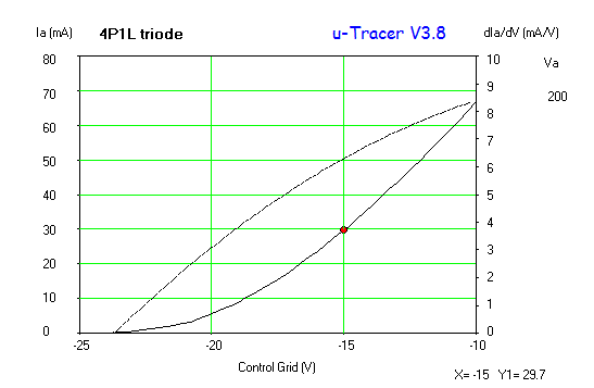
4P1L: Tracing A2 curves (first test)

Just finished the digital tracer project uTracer V3. Did some further tests this morning, now with my favourite DHT: 4P1L.

Started with a well known bias point for triode-strapped operation:

4P1L Va=200V Continue reading “4P1L: Tracing A2 curves (first test)”

4P1L triode SPICE model

After playing for some time with Dmitry’s great DHT composite triode models, I looked at refining the model by matching my own set of curves of the 4P1L in triode-mode. Here is my take on it:

4P1L Triode Model Continue reading “4P1L triode SPICE model”