46 DHT driver final tests

20130105-125459.jpg

Having built the 4P1L filament bias driver stage in a breadboard, I now have the sufficient voltage swing to drive the 46 to maximum sweep. In my 4-65a SE amp, a maximum of 200Vpp is required to drive the amp into class A2.

The following tests conditions were used:

  • 4P1L first stage:
    • DN2540 gyrator in mu follower output
    • 220nF/450V Capacitor coupled into 46 driver
    • Filament bias: 15 ohms, Vgk=-10V
    • Vsupply=355V and Va0=210V
    • Output set to about 30-32Vpp to drive 46 at 200Vpp
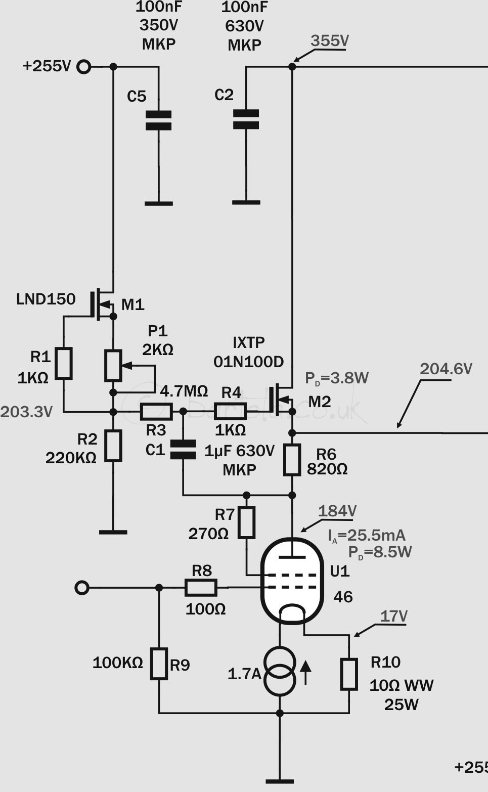
  • 46 driver stage:
    • IXYS 01N100 gyrator in mu follower output
    • Load impedance is 100K (Pete Millett’s interface)
    • Filament bias: 10 ohm / 100W Vgk=-17V
    • Vsupply=355V and Va0=204-208V
    • Output set to 200Vpp

I tested 28 valves. Just a few of my lot are NOS. The average THD was about 0.4-0.5% but a good selection of 8 valves (mainly Sylvania NOS) provided a consistent 0.18% THD:

4P1L into 46 driver test2Happy now with the initial tests and selection of 46 pairs for the amplifier, I can now continue with the build…

4-65a SE Amp: refining the 46 driver


I did some tests today and looked at minimising distortion of this 46 driver in filament bias and found that Va=230V (instead of 184V) to provide best performance:20130101-134450.jpgFilament bias resistor array is now laid out horizontally to improve the dissipation of heat.

Here is the performance (0.05% at 17Vrms) at maximum drive input from my audio test set:

46 Driver Test2 17Vrms


4-65a SE Amp: testing the 46 driver

46 driver breadboarded. The mu-follower gyrator, the filament bias resistor array and the nice teflon UX5 socket from Jakeband. The filament bias resistor array is formed by 4 10Ω 20W dale wirewound resistors. These get very hot so probably need to think an alternative layout or further resistors in parallel:20121231-191140.jpgThe performance is very good. I just picked up a random 46 from my stock and biased it at 204V (which is the operating point in my design) achieving less than 0.05% at 10Vrms. Need to re-run this test to see how will perform at 70Vrms:46 Driver Test1 10Vrms

20121231-191152.jpg

20121231-191204.jpg

Using my spice model created from a good 46 valve, THD should be around 0.15% at 200Vpp with a 100K load and performance is great to loads down to 100 ohms. Clearly the load in A2 will change from high impedance to some kΩ so this driver should maintain outstanding linearity all the way through:
46 driver THD

4-65a SE Amp: 46 Driver Gyrator

 A day of PCB etching

20121230-194358.jpgAfter a lot of work today in designing many PCBs, I finally got a pair of mu-follower MOSFET gyrators for the 46 driver stage.  The driver has to provide very low impedance to operate the 4-65a output valve in class A2. The gyrator in mu-follower configuration will enable the right bias point as the amplifier is DC coupled as well as maximum signal (and current in A2) with minimum distortion.

Many don’t like sand at all in their amplifiers. I have a lot of experience with gyrators and CCS loads in pre-amps and drivers as well. I have to say that with MOSFETs gyrators the sound is really nice. For an A2 driver, not many options are available and the gyrator is a great choice for this job.

I built two PCBs (one per channel) and the circuit is the classic depletion-mode MOSFET gyrator based on the high-voltage IXTP01N100D. I guess that a DN2540 should work as well here but I’ve been saving the IXYS for this occasion. The reference voltage for the anode bias point is provided by the CCS formed by M1 (LND150) which provides a higher impedance in AC improving the frequency response of the gyrator.

4-64-65a driverThe 46 is operating in triode-mode and filament bias with a Rod Coleman filament regulator. R6 is approximately 1/gm and output voltage is set by P1 to achieve the 4-65a bias point as the amplifier has stacked power supplies given coupling is DC, so no capacitors in the path to the grid.

Next: some tests on these gyrators and the filament boards…


4-65a SE Amp: 46 Driver Raw Supply

One more filament raw supply completed today: the 46 driver in filament bias. This driver stage requires 26V @ 1.7A due to the filament bias requirements. Yes, nearly 45W in the filament but will provide a fantastic driver stage with the 46 triode-strapped and filament bias to avoid any nasty capacitor in the signal path.

The power supply design is very simple and follows Rod Coleman’s recommendations for the DHT filament regulators. One drawback in this version, compared to the output stage raw supply, is that this will be pure capacitor filtering with no help of a choke to reduce the input current pulses.

4-65a 46 driver filament raw


The split-bobbin 150VA transformer provides sufficient current for the capacitor input filtering stage. The DSB10I45 (Schottky 45V/10A) bridge is also mounted on a “L” shape aluminium piece.IMG_3591

The capacitor arrays are soldered to a thick bare wire which provides structure and simplifies connections between components: IMG_3592

I was initially concerned that without shielding the high-current pulses may introduce some noise in the output as F2 fuse is mounted on the transformer frame so the wire is routed back and forward to that point. Reality is that the hum level is very low. I measured 16.4mV peak-to-peak at full load.


4-65a SE driver

46 DHT in triode mode as a driver

46 driver THD analysis

Continuing with the design of the 4-65A SE amplifier based on M. Koster design, I’m in the process of tweaking the 46 driver to optimise the operating point and provide maximum distortion to drive the demanding 4-65a. Here is the circuit I’m currently working on.

The current 46 driver will be biased at around 25-30mA using filament bias, so Vgk will be around -16 to -17.5V using a 10Ω filament bias resistor array. This will set the 46 at around 185-210V which will give sufficient headroom (i.e. need about 200Vpp max) to drive the 4-65a.

So today I look at varying slightly both anode currents and Vgk to see impact on THD.

So minimum THD is around -17V and Ia=30mA. So if setting the Rod Coleman filament regulator to ensure that Vgk=-17V and the anode gyrator to set anode voltage to ensure Ia is close to bias current would provide the minimum distortion (which is 0.04% in this example). Pa is close to 7W, but looking at the datasheet we can see that maximum Pa is 10W (as the latter 45 version).

46 Super Silvertone THD


So next I need to build a prototype of this driver with filament regulator and gyrator load.

Valve THD analysis

Measuring triode linearity

Today decided to do a quick distortion test of on a sample of a variety of different valves. All either triodes or triode-strapped pentodes/tetrodes. As per my previous tests, distortion was measured at +22.22dBu (10 Vrms) at the output of the valve in common-cathode mode. Valves were loaded with the CCS I use in my curve tracer. The operating points were quickly optimised at hand, so I’m sure there may be some better operating points for some of the valves below which may improve their overall THD. If you have any suggestions, please let me know!

Tested valves for THD
THD analysis

Need to retake these measures as the soundcard interface got damaged and results are showing significant distortion

Interesting to see in the chart above, that 6e5p and 6C45p are the best ones. This is in line with their reputation as drivers as they are capable of swinging many volts and producing very low distortion. In terms of harmonics I noticed that 6e5P provides a richer H3 and H5 as being a triode-strapped valve, whereas the 6c45p provide a dominant H2.

Also good to see that my favourite 46, 4P1L and 6CB5A (all triode-strapped) are very linear with anode currents of 40mA (with the exception of 46 as I measured THD on a previous operating point used for transconductance measurement). I should retake the 46 and drive it harder, I’m sure it will perform better at higher current.

Surprised with the results of the 6N6P-I. Was expecting this one a bit better, but perhaps it’s the pulse version distortion, so may need to get hold of an 6N6P and compare the results.

Update:
It looks like I blew up Pete Millett’s interface after measuring THD in float mode and exceeding the 10Vrms limit in this mode. Therefore measures such as 26, CX301a and others are not accurate. When testing 26 with my Ferrograph test set it came out to be 0.05%…
Stay tune until I repair the unit!

46 THD analysis

GM tester modified today to add an option to disconnect the CCS bypass capacitor so can drive the valve with an external signal and measure THD from output in common-cathode mode. The input is calibrated to produce 10Vrms (22.22dBu) at the anode and then signal is fed into the PC through the Pete Millet’s interface:

GM/THD tester

Did some sample tests with a set of lovely globe CX301a achieving THDs from 0.27% to 0.35%.

When looking at a driver valve such as 46 (triode-strapped) got THD values of around 0.05-0.09% for good valves. When picked up the faulty one I had discovered yesterday with the curve tracer, the THD shown to be 0.20% and over 0.35% in the worst one.

Need to retake these measures as the soundcard interface got damaged and results are showing significant distortion


20120604-122936.jpg
46 THD analysis

The PC generates a low distortion sine wave which is fed into the valve grid through the input capacitor. This is the same setup used for the transconductance test. The CCS in the anode is unbypassed to ensure the anode signal is not shunted to ground. The output is then taken out through the output PIO capacitor and fed back into the PC input adapter (Pete Millett’s sound card interface). Audiotester is used then to measure THD at 1kHz.

20120604-122954.jpg

Finishing the curve tracer


Today I did a bit of extra work on the curve tracer with a view of finishing it. It has been a long and painful journey, but I’m reaching the end of it.

Tracing curves with the oscilloscope4P1L under testCurve tracer and 10Y10Y under test

The transconductance tester is working perfect. I need to use the following ranges in my true RMS AC voltmeter:

  1. 0-2,000 μmho: 100mVrms scale
  2. 2,000μmho-50,0000μmho: 1Vrms scale

It’s probably the DC bias which affects the low scale. As an example when testing a 46 in triode mode (see datasheet for details), I tried the following operating point: Vg=-33V, Ia=22mA and the measure should be around 2.35 mVrms over 220mVdc. But in my bench voltmeter, above 17mA in the 46 doesn’t like it and cannot measure it, so need to change scale. I tested low transconductance valves in the lower AC scale such as CX301a, 26, 4P1L, 71a and then using the high AC scale, used 6e5P, 6C45, 6N6P amongst others.

The tracer now has a common-mode mains filter. This was required as at certain times during the day, specially in the evenings when the mains is really noise or my wife is using the microwave oven!, when tracing curves with the 1Ω sensing resistor and low anode currents (e.g. CX301a) then the noise level was sufficient to impact and distort the traced image. With the common-mode mains filter it works brilliantly.

Now need to place bottom plate and standing feet. Job done then and will move to some proper audio work!

Testing the circuit today, I measured 29 46 valves.  Ended up discarding two which measured low and then when tested with the tracer found that curves weren’t good at all. Probably electrode misalignment as they weren’t just with low transconductance. Will upload some examples as it’s very interesting to see the difference


Improved 46 triode-strapped DHT composite model

My initial attempt to get a reasonable SPICE model for a 46 triode-connected DHT has proven to be ok considering it was my first try. I got better accuracy with my second attempt using CX-301a. With time, I should learn the skills of Dmitry Nizh to master the great tool he has developed. For the ones who haven’t seen his website and great material Dmitry has produced around DHT, SPICE and other good stuff, I recommend you to read his article about composite models for DHT here.

Dmitry kindly produced a very accurate model for the 46 (and also shown clearly that I’m a still a rookie at this things ):

And here is the equivalent Spice model:

Using a simple circuit in LTspice we can test the model and trace the anode characteristic curves:

And the curves can be easily generated:


Note that grid voltage starts at 0V in -10V steps.